
Super Light Sensor

The circuit operates by detecting light level fluctuations through LDR1, with the resulting signal directed to comparator stage IC1. This comparator triggers timer IC2, configured as a monostable multivibrator, which subsequently activates transistor Q2 and a relay. The signal from the sensor is fed into the comparator IC1 through two 150 kΩ resistors. Due to the presence of a 220 nF capacitor, fluctuations in the signal experience a slight delay at pin 3 compared to pin 2. Consequently, the output at pin 6 of the comparator (IC1) switches low during brief signal fluctuations, thereby triggering the monostable timer IC2. This timer, in turn, activates transistor Q2, which engages Relay 1 and illuminates LED1 via a 1.5 kΩ current-limiting resistor. A trimpot (VR2) allows for adjustment of the monostable period, ranging from approximately 3 seconds to 30 seconds.
The Super Light Sensor may exhibit reduced performance under AC lighting compared to natural lighting. If AC lighting interferes with operation, a 16 µF (16V) electrolytic capacitor can be connected between the sensor output and ground to filter the signal before it reaches the comparator. When pin 3 of IC2 transitions high, FET Q1 is activated, pulling pin 2 of IC2 high. This state remains for a brief period after pin 3 returns low, facilitated by a 100 nF capacitor at the gate of the transistor. This "blanking" period allows the circuit to stabilize after the relay disengages, preventing current draw during this time. The blanking also enables external circuits to share the same power supply without interfering with the Super Light Sensor's operation. The circuit consumes less than 10 mA in standby mode, making it suitable for battery operation, such as using eight AA batteries.
After assembly, the circuit should be powered on and allowed to stabilize. The sensitivity can be fine-tuned using VR1 to achieve optimal performance without false triggering. With experimentation, the circuit can adapt seamlessly between natural and AC lighting conditions. If the highest sensitivity for natural lighting results in false triggers under AC lighting, VR1 can be adjusted to maximize sensitivity for AC conditions and vice versa. Under daylight, the Super Light Sensor can detect a moving finger from a distance of 3 meters without lenses and can sense a person crossing a path from more than 10 meters away, also without lenses. When configured as an active system, it can detect a person walking in front of a standard light source (e.g., a 60W incandescent bulb) from distances exceeding 10 meters. These detection ranges are enhanced by placing the LDR within a black tube, as illustrated in the accompanying figure. Utilizing a single lens can double these distances, while employing two lenses in an active configuration can increase the basic range by a factor of six or seven.This "Super Light Sensor" responds to minute fluctuations in light level, auto-adjusting over the range from about 200 lux up to 60, 000 lux (ie, from a modestly lit room to direct sunlight). It has lots of potential uses - eg, detecting a car entering a driveway, a person moving in a room, or wind rustling the leaves of a tree.
At the same time, i t has a high level of rejection of natural light variations, such as sunrise, sunset and the movement of clouds. While it is a "passive" system, it can also be used as an "active" system - ie, used in conjunction with a light beam.
Its great advantage here is that, since it responds to fluctuations in light level rather than the crossing of a specific light threshold, it is much more flexible than other typical "active" systems. It can be placed within the line-of-sight of almost any light source, including "vague" ambient light, and simply switched on.
As shown, the LDR is wired as part of a voltage divider so that, between darkness and full sunlight, its output at "X" varies between about one-quarter and three-quarters of the supply voltage. A wide variety of sensors may be used in place of the LDR, including photo-transistors, photo-diodes and infrared and ultraviolet devices.
Fig. 1: light level fluctuations are detected by LDR1 and the resulting signal fed to comparator stage IC1. IC1 in turn triggers 7555 timer IC2 which is wired as a monostable and this drives transistor Q2 and a relay.
The signal from the sensor is fed to the inputs of comparator IC1 via two 150kO resistors. However, any signal fluctuations will be slightly delayed on pin 3 compared to pin 2, due to the 220nF capacitor. As a result, the pin 6 output of the comparator (IC1) switches low during short-term signal fluctuations and this triggers monostable timer IC2.
IC2 in turn switches on transistor Q2 which activates Relay 1. It also lights LED1 via a 1. 5kO current-limiting resistor. Trimpot VR2 allows the monostable period to be adjusted between about 3s and 30s. As with all such circuits, the Super Light Sensor may not work as well under AC lighting as under natural lighting. If AC lighting does prove a problem, a 16 µF (16V) electrolytic capacitor can be connected between the sensor output and ground to filter the signal to the comparator.
When pin 3 of IC2 goes high, FET Q1 also turns on and pulls pin 2 of IC2 high. This transistor remains on for a very short period after pin 3 goes low again due to the 100nF capacitor on its gate. This "blanking" is done to allow the circuit time to settle again after the relay disengages (and stops drawing current).
The "blanking" also makes it possible to run external circuits from the same power supply as the Super Light Sensor, without upsetting the circuit. The current consumption is less than 10mA on standby, so that battery operation (eg, 8 x AA batteries) is feasible.
After building the circuit, switch on and wait for the circuit to settle. It`s then just a matter of adjusting VR1 so that the circuit has good sensitivity without false triggering. With some experimentation, it`s possible to set the circuit to change seamlessly from natural to AC lighting.
If maximum sensitivity under natural lighting false triggers the circuit under AC, then adjust VR1 to give maximum sensitivity under AC (and vice versa). In daylight, the Super Light Sensor will typically detect a single finger moving at a distance of 3m, without the use of any lenses.
It will also detect a person crossing a path at a distance of more than 10m, again without lenses. And when used as an "active" system, it will typically detect a person walking in front of an ordinary light source (eg, a 60W incandescent light-bulb) at more than 10m. Note that these ranges are achieved by placing the LDR (which is used as the light sensor) in a black tube, as shown in Fig.
2. A single lens will double these distances, while the use of two lenses in an "active" system will multiply the basic range by 6 or 7. 🔗 External reference
Related Circuits

This light sensor switch circuit enables the automatic activation of a lamp when ambient light levels decrease, such as during nightfall. The duration for which the lamp remains on can be adjusted using potentiometer P1, with a range of...

This design circuit is for audio graphic equalizers, which are commonly found in commercial products, yet circuits for them are rarely published. The circuit features a simple design that requires an operational amplifier (op-amp) to amplify the input signal....
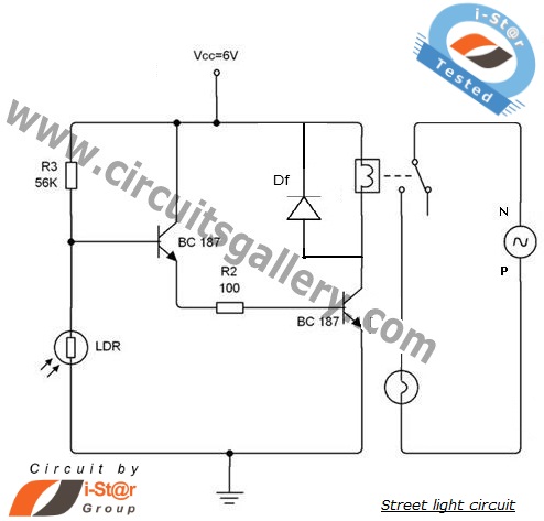
An automatic street light system is increasingly common, providing an intelligent mechanism for street lighting. It automatically illuminates during the night and utilizes incandescent lamps instead of LEDs for energy savings. This document outlines the process of constructing an...
The general-purpose circuit of the simple pressure sensor alarm is constructed using a few easily accessible and inexpensive components. The operation of this circuit is straightforward. The simple pressure sensor alarm circuit typically includes a pressure sensor, an operational amplifier...
This is a Courtesy Light Extender for vehicles. It extends the ON time of the interior lights when a door is closed, allowing passengers to see where they are seated. The Courtesy Light Extender circuit is designed to enhance the...
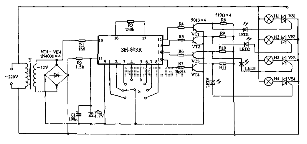
22V AC is supplied through thyristors VSl to VS4 for lighting control. The current is routed through transformer T, followed by rectification using diodes VD1 to VD4, and regulated by VD5 to provide a filtered output of approximately 4.7V...