
SUPER SIMPLE SHORTWAVE RECEIVER

The NE602 double-balanced mixer is designed for use in various RF applications, providing effective signal processing capabilities. The circuit begins with the antenna input (J1), where RF signals are received. These signals pass through the DC-blocking capacitor (C1), which prevents any DC voltage from affecting the subsequent stages of the circuit, ensuring that only the AC signal is processed.
The RF-gain control (R1) allows for the adjustment of the signal amplitude before it is fed into the mixer. This control is crucial for optimizing the performance of the mixer, as it can help prevent saturation and distortion of the output signal. The mixer itself, U1, combines the incoming RF signal with a local oscillator signal generated internally.
The local oscillator frequency is determined by the values of the resistor (R2) and inductor (L2). Adjusting these components allows for fine-tuning of the oscillator frequency, enabling the circuit to operate across a range of frequencies as required by the application. The internal mixing process results in the generation of intermediate frequencies (IF) that can be further processed or demodulated, depending on the application.
Overall, the NE602 mixer circuit is a versatile and essential component for RF signal processing, capable of handling a variety of signal types and frequencies while providing adjustable gain and frequency settings.Integrated circuit U1 (an NE602 double-balanced mixer) is a combination oscillator and frequency mixer. Signals from the antenna input (at J1) are fed through dc-blocking capacitor C1 to the RF-gain control, R1, and fed to the input of U1 at pins 1 and 2.The local-oscillator frequency, which varies with the settings of R2 and L2, is mixed internally within U..
🔗 External reference
Related Circuits
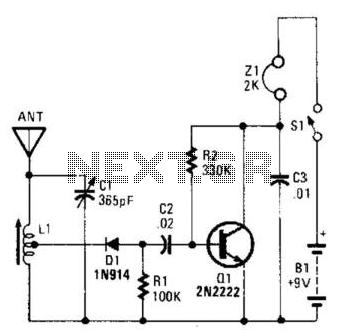
An AM radio can be constructed using a simple diode detector and an audio amplifier. A random length of wire typically serves as an antenna. LI is an adjustable ferrite loopstick similar to those used in transistor radios. An AM...
This is a simple phono preamplifier circuit diagram. In recent years, following the introduction of CDs, vinyl recordings have almost disappeared. Nevertheless, a phono preamplifier remains useful for listening to old vinyl discs from a well-preserved collection. This simple...
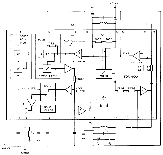
GENERAL DESCRIPTION The TDA7000 is a monolithic integrated circuit designed for mono FM portable radios or receivers, emphasizing minimal peripheral components to achieve compact dimensions and reduced costs. This integrated circuit features a Frequency-Locked-Loop (FLL) system with an intermediate...
Similar to the CMOS-based touch switch available on this site, this transistor-based touch switch can activate a load simply by the user touching a metal plate. It is designed to directly switch a relay, allowing it to be used...
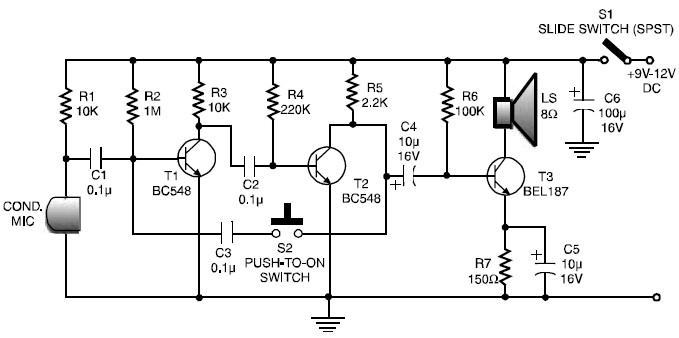
This is a low-cost and simple intercom circuit design that utilizes three transistors. Even a novice can assemble it on a piece of veroboard without difficulty. The intercom circuit is designed to facilitate two-way audio communication between two locations. The...
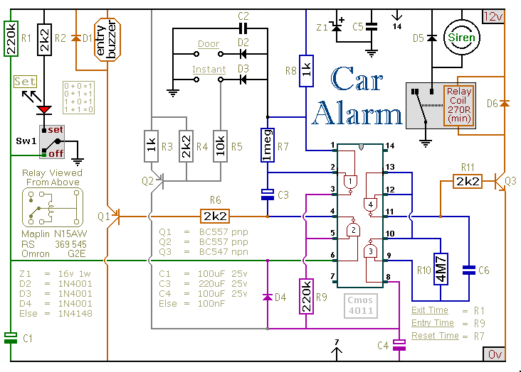
This circuit includes automatic exit and entry delays, an optional instant alarm zone, an optional intermittent siren output, and an automatic reset feature. By incorporating external relays, it is possible to immobilize the vehicle and activate the lights. For...