
Understanding Circuit Schematics

The circuit in question involves a schematic where pin 2 and pin 6 are interconnected. To fully understand the implications of this connection, it is essential to analyze the roles of these pins within the broader context of the circuit.
Pin 2 may serve as an input or control signal, while pin 6 could function as an output or feedback point, depending on the specific application of the circuit. The connection between these two pins suggests a potential interaction that may influence the circuit’s performance, such as signal conditioning or control logic.
In examining the schematic, it is crucial to identify the components associated with these pins. For instance, if pin 2 is connected to a resistor or capacitor, this could affect the timing characteristics or the impedance seen by the signal. Additionally, understanding the voltage levels and current flow between these pins can provide insights into the overall functionality of the circuit.
Further investigation into the surrounding components, such as transistors, operational amplifiers, or digital logic gates, will yield a more comprehensive understanding of how pin 2 and pin 6 interact. It is also advisable to refer to the datasheet or technical documentation for the specific components involved to clarify their operational parameters and constraints.
Ultimately, a thorough analysis of the schematic, including the identification of all relevant connections and components, will facilitate a clearer understanding of the circuit's behavior and the significance of the connection between pin 2 and pin 6.Here is a schematic that I need help understanding- On this circuit I`m assuming pin 2 is connected by a wire to pin 6 even though it doesn`t make.. 🔗 External reference
Related Circuits
This inverter is very easy to construct, reliable, and even powerful enough to light up a 15W fluorescent tube (if you cool your transistor well). The only hard-to-find piece of this baby is the so-called yellow inverter transformer. It's...
Bistable circuit operating at a frequency of 100 kHz or less. A bistable circuit, also known as a flip-flop, is a type of electronic circuit that has two stable states and can be used to store binary information. This circuit...
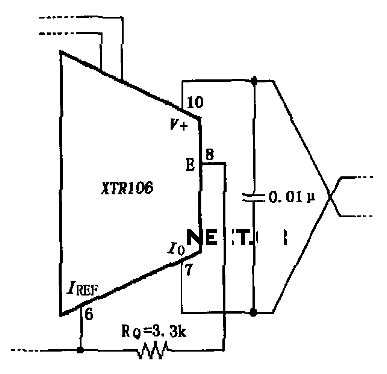
The circuit has been simplified due to the cancellation of an external transistor. The connection between the emitter terminals of the original external transistor and a 3.3k resistor will be removed, as this change has led to a decrease...
The only drawback of a single operational amplifier (op-amp) stage is that it inverts the signal, necessitating an additional inverting buffer to restore the original phase if absolute phase is a concern. Various schematics exist for both configurations, but...
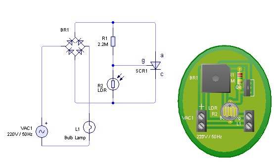
Adjust the value of R1 to achieve optimal performance of the LDR sensor. If, in practice, a resistance of 2.2 MΩ still activates the lamp, it is possible to increase the value of R1 to a larger resistance of...
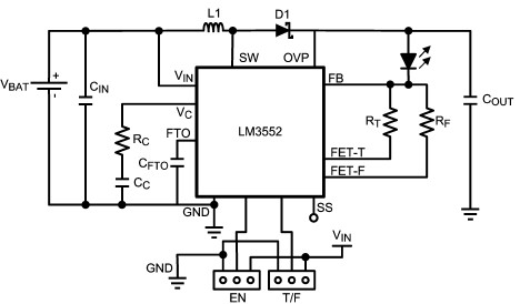
For this LED driver electronic project, a DC power supply circuit is required to provide an output voltage between 2.7V and 5.5V. The supply voltage must be applied between Vin and GND. The T/F jumper connects the T post...