
Universal DC-DC Convertor

The described circuit functions as a simple DC-DC converter, utilizing a Zener diode to achieve voltage regulation. The primary components of the circuit include a 12V DC input source (such as a battery), a resistor, and a Zener diode configured in reverse bias.
When the circuit is powered, the 12V input voltage is applied across the series resistor and the Zener diode. The resistor's value is selected to limit the current flowing through the Zener diode to a safe level, ensuring that the Zener operates within its specified limits. The Zener diode is chosen based on the desired output voltage; in this case, a Zener diode rated for 9V is used to regulate the output voltage.
The Zener diode maintains a constant voltage across its terminals when reverse-biased, effectively clamping the output voltage to the Zener voltage. This allows the circuit to provide a stable 9V output from the 12V input, as long as the input voltage remains above the Zener breakdown voltage and the current through the diode remains within the specified range.
For applications requiring different output voltages, the Zener diode can be replaced with one of a different rating. Additionally, the resistor may need to be recalculated to ensure proper current limiting for the new Zener diode. It is essential to consider the power rating of the Zener diode and the resistor to prevent overheating and ensure reliable operation.
Overall, this circuit design is suitable for low-power applications where a simple and adjustable voltage regulation solution is required, making it versatile for various electronic projects and devices.This circuit will generate a smaller DC output voltage from a larger DC input voltage.It is quick and simple to make and by changing the value of the zener diode, the circuit can be universally adapted to provide other output voltages.The circuit and all diagrams represent a DC convertor with 12V battery input and 9Volt DC output. 🔗 External reference
Related Circuits
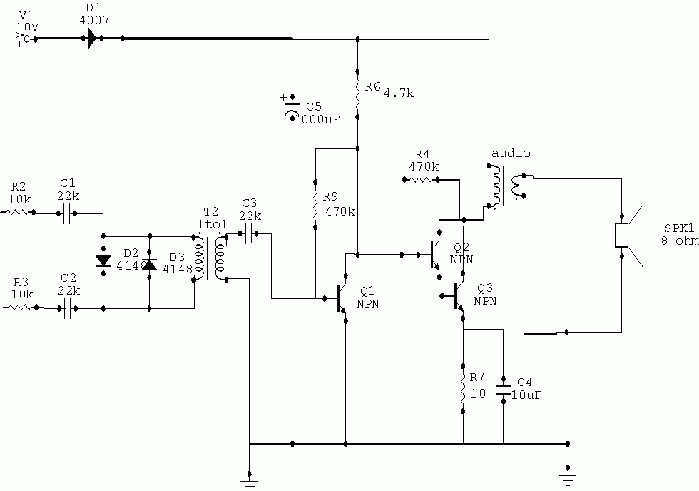
Briefly it's an Infrared receiver which communicated with your pc to command many windows application, so once you have built the interface, programmed the pic16f84 with the code and connected everything to your serial com2 you'll be able to...
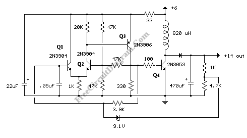
A DC-to-DC step-up converter is typically implemented using a transformer, which converts DC voltage to AC voltage, steps it up with the transformer, and then rectifies and filters the output to achieve a higher DC voltage. However, a voltage...
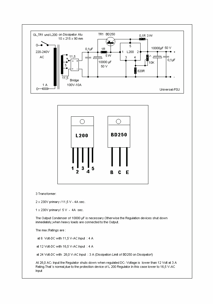
A Universal Power supply based on the L200 regulator, which includes an outboard pass transistor to boost output currents up to 4 amps. The described universal power supply circuit utilizes the L200 voltage regulator, a versatile component capable of providing...
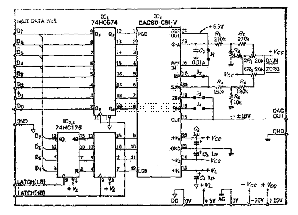
The 8 microcomputer data operates with an 8-bit parallel output, while also accommodating serial input for D-A converters. Typically, data must be entered in two groups and processed as a whole. The requirements for data latching involve 16 straight...
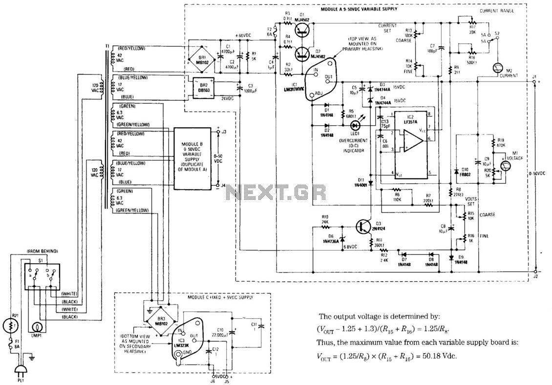
The design's value is derived from the use of IC1, an LM317HVK adjustable series-pass voltage regulator, which provides broad-range performance along with voltage-setting and current-limiting functions. The input to IC1 is sourced from the output of BR1, which is...
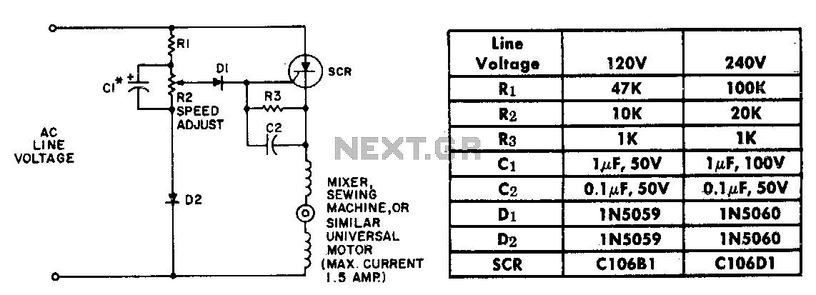
The resistor-capacitor network R1-R2-C1 generates a ramp-type reference voltage that is superimposed on an adjustable DC voltage controlled by the speed-setting potentiometer R2. This reference voltage, available at the wiper of R2, is compared against the residual counter electromotive...