
Universal motor speed control

The described circuit employs a resistor-capacitor (RC) network consisting of resistors R1 and R2, and capacitor C1, which collectively create a ramp voltage signal. This ramp voltage is essential for modulating the control of a motor's speed, particularly in applications where load variations are common. The speed-setting potentiometer R2 plays a critical role in adjusting the amplitude of the reference voltage, allowing for fine-tuning of the motor's operational characteristics.
The interaction between the ramp voltage and the motor's counter emf is crucial for effective motor control. As the motor load increases, resulting in a reduction of counter emf, the ramp voltage triggers the SCR at an earlier point in the AC cycle. This early triggering increases the voltage applied to the motor, compensating for the drop in speed caused by the heavier load.
The choice of the C106 SCR is significant due to its low trigger current requirement, which allows the circuit to utilize a flat top reference voltage. This design choice enhances the feedback gain, providing a more stable and responsive control mechanism. The flat top reference voltage contributes to improved speed regulation, ensuring that the motor can maintain its desired speed despite fluctuations in load conditions.
In summary, the combination of the RC network, speed-setting potentiometer, and SCR provides an efficient method for controlling motor speed, with particular attention to maintaining performance under varying load conditions. The overall circuit design emphasizes reliability and precision, making it well-suited for applications requiring consistent motor operation.The resistor capacitor network R1-R2-C1 provides a ramp-type reference voltage superimposed on top of a dc voltage adjustable with the speed-setting potentiometer R2. This reference voltage appearing at the wiper of R2 is balanced against the residual counter emf of the motor through the SCR gate.
As the motor slows down due to heavy loading, its counter emf falls, and the reference ramp triggers the SCR earlier in the ac cycle More voltage is thereby applied to the motor causing it to pick up speed again. Performance with the C106 SCR is particularly good because the low trigger current requirements of this device allow use of a flat top reference voltage, which provides good feedback gain and close speed regulation.
Related Circuits
DC motors can be operated remotely using controls transmitted via an RF module. This circuit employs an RF module to manage DC motors through a motor driver integrated circuit (IC) L293D. Transmission is initiated by setting pin 14 (TE,...
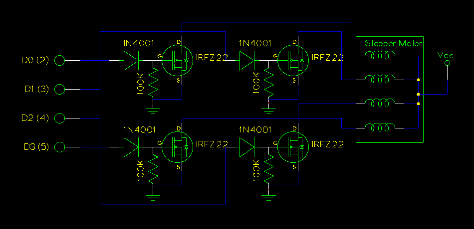
The use of a PC's parallel port provides a convenient method for controlling a stepper motor. For unipolar stepper motors, it is possible to control up to two motors using the 8-bit data line. Typically, a Darlington driver, such...
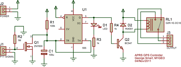
The Yaesu FT-7900E radio's power status can be utilized to manage the power status of the GPS and Tracker without requiring additional cabling. If implemented correctly, this would enable the radio's Auto-Power-Off feature to also turn off the GPS...

Any number of normally-open switches may be utilized. Install "tilt" switches that close when the steering is moved or when the bike is lifted off its side-stand or pushed forward off its centre-stand. Employ micro-switches to secure removable panels...
This circuit is designed for an electrically operated rolling shutter, typically featuring a standard control panel with a three-position switch: up, down, and stop. To automate the opening and closing with a time-controlled switch, additional wiring connections are required....
This circuit allows for the adjustment of fan speed from a distance, such as from a couch or bed. It utilizes the TSOP1738 infrared receiver module to capture the infrared signals. The circuit operates by employing an infrared remote control,...