
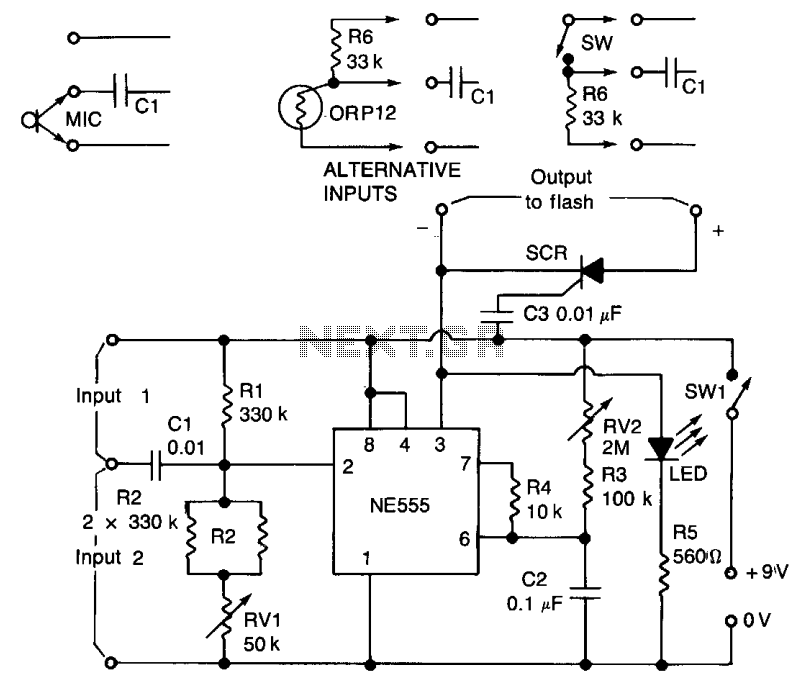
Universal electronic timer circuit diagram

The described circuit functions as a flexible timer, suitable for various applications requiring precise timing control. The NE555 timer is a widely used integrated circuit that can generate accurate timing pulses, making it ideal for this application. The use of the CD4017 decade counter allows for easy extension of timing intervals by counting pulses generated by the NE555. The combination of resistors R1 and R2 provides the ability to fine-tune the timing period, while the capacitive element C3 ensures stability in the timing operation.
The circuit's AC control is facilitated by the TRIAC, which allows for switching high power loads safely. The BG control mechanism ensures that the TRIAC is only activated when necessary, conserving energy and prolonging the lifespan of the components. The inclusion of a simple DC power supply circuit ensures that the timer operates reliably with a stable voltage source.
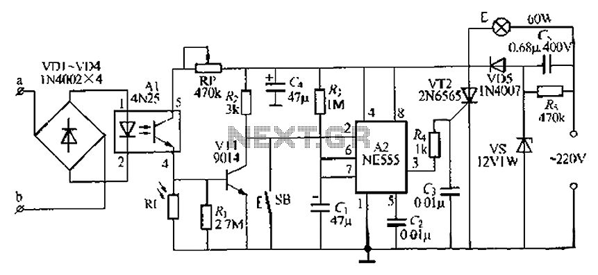
The design is modular, allowing for easy adjustments and expansions. The use of relays for the timing control provides a robust solution for managing different timing cycles, further enhancing the versatility of the timer. Overall, this circuit represents a practical solution for applications requiring a reliable and adjustable timer, capable of managing both short and extended timing intervals efficiently.Figure 1-1 The general-purpose timer once timing of 5 minutes to 18 hours; the timing cycle from 5 minutes to 20 hours; the total time of the timing and the timing to open and close 18 hours. Controlling power of 500W or less, the circuit power consumption is less than 1W. Time base circuit NE555 and C3, W, when R1, R2 constituting the base pulse generating circuit. W can adjust the pulse period from 5 minutes to 2 hours between changes. R2 extended from the pulse period of action. R2 is the longest period without a pulse for 1 hour. CD4017 counter and D2-D10, K1-K10 delay multiplier circuit and other components. The circuit will extend a total of 10 times the pulse period. K1-K10 control multiplication factor, and the NE555 output pulse period was logarithmic plot. BG and triac control circuit constituting the AC power. BG group high level conduction, SCR is triggered conduction, controlled circuit. BG base to very low cut-off, SCR is turned off, the controlled circuit to stop working. C1, DW, D11, C2 composed of simple DC supply circuit to provide 12V DC power for the timing circuit. When a timer, K12 set to 1 at the, K1 open. NE555 pulse output 10 after, CD4017s EN is high and stop counting. Then click the AN, CD4017 counted once again, once the timing up to 18 hours. When the timing cycle, K12 put 2, CD4017 cycle count. Each time through the loop the longest 20 hours. Timing of opening and closed by a timing control K1-K10.
Related Circuits
The lamp base circuit integrates an NE555 timer and optocouplers to automatically activate the light when a phone call is received at night. The lamp will self-extinguish after a delay. Additionally, a switch allows manual control of the lamp....
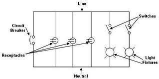
Each component of the circuit is represented in a simple block form with corresponding labels for identification, using no special symbols or language. The interconnections between these components are depicted by solid lines. The block diagrams can be read...
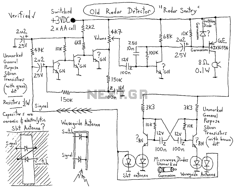
This integrated circuit (IC) requires fewer external components, making it simpler for beginners to assemble it on a veroboard. The original circuit was sourced from its datasheet. A slightly modified version of the circuit is presented below. This circuit...
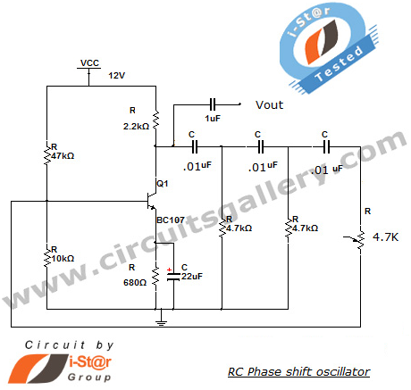
This section introduces a transistor oscillator circuit known as the RC Phase Shift Oscillator. An oscillator is an electronic circuit that functions as a sine wave generator, requiring only a DC power supply. It is commonly used in variable...
A 12V battery charging circuit is presented, featuring a straightforward diagram for a rectifier. The lead-acid trickle charger circuit is detailed along with its rectifier. The 12V battery charging circuit is designed to charge lead-acid batteries using a trickle charging...
A negative pulse at the input is fed through capacitor C1 to the input pin (2) of the integrated circuit (IC). Pin 2 is maintained slightly above its triggering voltage of 1/3 Vcc by a voltage divider consisting of...