
universal high resistance voltmeter

The universal high-input-resistance voltmeter circuit is designed to offer flexibility in measuring various voltage types, including direct current (DC) and alternating current (AC) in different forms such as root mean square (RMS), peak, and peak-to-peak values. The operational amplifier (op-amp) serves as the core component, providing high input impedance, which minimizes the loading effect on the circuit being measured.
The function switch in the circuit allows users to select the desired measurement type, effectively configuring the circuit for optimal performance depending on the application. The full-scale deflection current rating (IFS) is crucial for ensuring that the microammeter displays accurate readings, and it is determined by the specific resistor value used in conjunction with the op-amp.
The bridge rectifier converts AC signals into a DC format, facilitating easier measurement with the microammeter. By adjusting the resistor connected to the inverting input of the op-amp, the circuit can be calibrated to accommodate different voltage ranges, enhancing its versatility.
In practical applications, the non-inverting input of the op-amp is connected to the voltage source under test, while the inverting input is linked to ground through the adjustable resistor. This configuration allows the op-amp to amplify the input signal, providing a clear and precise reading on the microammeter, which is essential for accurate voltage measurements across various scenarios.
Overall, this circuit exemplifies an efficient design for voltage measurement, combining essential components to achieve a wide range of functionalities while maintaining high accuracy and reliability.The full-scale deflection of the universalhigh-input-resistance voltmetercircuit shown in the figuredepends on the function switch positionas follows: The term IFS in the aboveequations refers to meter`s fullscaledeflection current rating inamperes. It must be noted that neithermeter resistance nor diode voltagedrops affects meter current. A high-i nput-resistance op-amp, abridge rectifier, a microammeter, and afew other discrete components are all thatare required to realise this versatile circuit. This circuit can be used for measurementof DC, AC RMS, AC peak, orAC peak-to-peak voltage by simply changing the value of the resistor connected betweenthe inverting input terminal of theop-amp and ground.
The voltage to bemeasured is connected to non-inverting inputof the op-amp. 🔗 External reference
Related Circuits
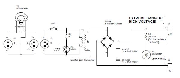
Transformers designed for powering large neon signs are cost-effective and highly reliable. Typically, the secondary winding is center-tapped, which restricts the full utilization of its peak-to-peak output in scenarios where one terminal must be grounded. In the power supply...
This circuit incorporates a datasheet-compliant trigger signal, reversed polarity protection, an optional test button, and the capability for battery operation. It utilizes either the U1 L601E3 or MAC97A8 triac, rated for 400 V and 1 A. When U1 is...
The contact resistance measuring circuit is illustrated in the figure. It primarily consists of a constant current circuit and an amplifying circuit. Operational amplifier IC1 is configured as a voltage follower, and the voltage across the load equates to...
The 1N4001 is a 1 Amp silicon rectifier with a voltage range of 50 to 1000 volts. It features guaranteed high-temperature soldering, high current capability, a diffused junction, low reverse leakage, and utilizes a void-free molded plastic technique for...
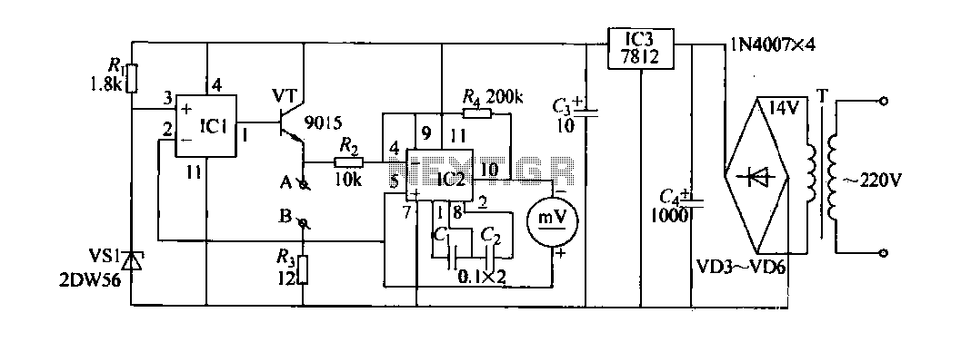
Voltage variations and power cuts adversely affect various equipment such as TVs, VCRs, music systems, and refrigerators. This simple circuit will protect the costly equipment from high as well as low voltages and the voltage surges (when power resumes)....
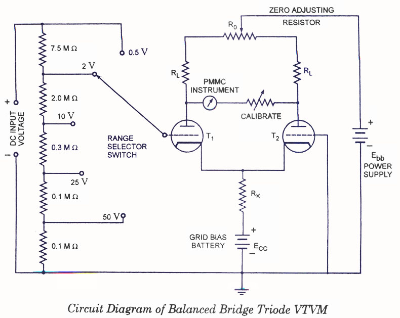
Voltmeters can be utilized for measuring both direct current (DC) and alternating current (AC) voltages and are widely used. These voltmeters are available in two types: vacuum tube and transistorized. In the vacuum tube version, two identical triodes, T1...