
Universal Power Controller

In this circuit design, Relay K1 serves as a critical control element that isolates the sensor from the main load circuit. The low-impedance coil of K1 allows for quick activation with minimal current draw, making it efficient in responding to sensor signals. When the sensor detects a condition that requires action, it opens, and this opening allows current to flow through K1's coil. The relay activates, and its contacts change state, which in turn opens the circuit to the load managed by Relay K2.
The main relay K2, characterized by its high-impedance coil, is designed to handle larger loads, such as those required for HVAC systems. The high impedance ensures that K2 only activates when K1 is in a specific state, thus preventing unwanted activation of the load during transient conditions. The interaction between K1 and K2 is crucial; K1's contacts must open to limit the current flowing to K2, ensuring that the load is only powered under safe and appropriate conditions.
Overall, this relay configuration provides a robust solution for controlling high-power devices based on sensor inputs, enhancing both safety and efficiency in electrical systems. The design effectively prevents feedback from the load circuit, ensuring that sensor state changes do not inadvertently affect the operation of the load, thereby maintaining system stability and reliability. Relay K1 has a low-impedance coil and K2 has a high-impedance coil. When a sensor opens, current is routed throu gh the coil of Kl. K1 activates, opens its contacts, and prevents a sensor contact reclosure from affecting the circuit. When Kl contacts open, current to the main relay K2 is limited by the impedance of Kl. 2 controls power to a load (air conditioner, furnace blower, etc.).
Related Circuits

This article continues from the previous one regarding the single character LCD display using an AVR microcontroller. The prior article demonstrated how to display a single letter on an LCD. This article advances the learning process by explaining how...
The TPS3803 and TPS3805 families of supervisory circuits offer circuit initialization and timing supervision, mainly for digital signal processors (DSPs) and processor-based systems. The TPS3803G15 device features a fixed-sense threshold voltage (VIT) determined by an internal voltage divider, while...
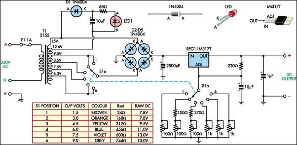
The following circuit illustrates a Battery Replacement Power Supply Circuit Diagram. This circuit is based on the LM317 integrated circuit. Features include the ability to replace... The Battery Replacement Power Supply Circuit utilizes the LM317 voltage regulator to provide a...
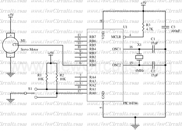
This simple micro-control circuit controls a servo motor according to a 3-state switch. A servo motor acts as an actuator in 3 positions. It has 3 wires, one for VCC, one for Ground, and another one for position control....
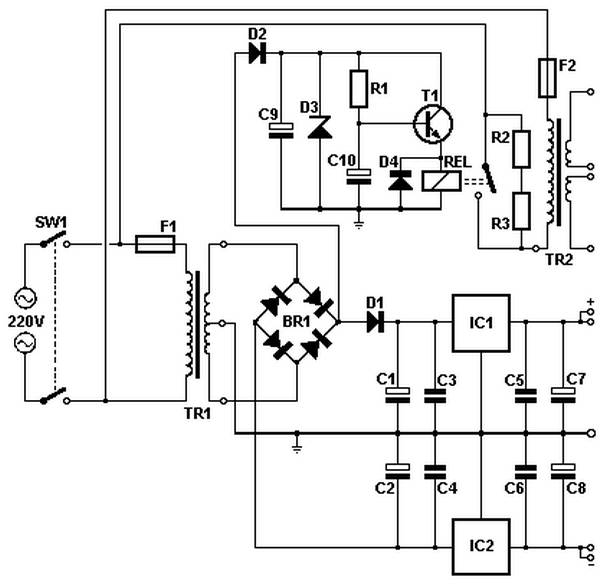
Soft power for a large transformer is implemented by using a series resistance of 100 ohms at 10 watts, or alternatively, two resistors of 47 ohms at 5 watts each in the primary circuit. The resistance is bypassed by...
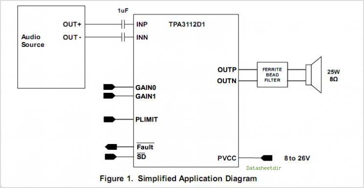
The combination of controller IC LM4651 and LM4652 Class D MOSFET power amplifier IC provides a high-efficiency solution suitable for powered speakers, subwoofers, and car amplifiers. The LM4651 is a fully integrated conventional pulse width modulator (PWM) driver, which...