
universal timer

The described circuit is a digital timer that utilizes a binary-coded decimal (BCD) format for setting the time interval via DIP switches. The circuit operates with a 120 Hz input signal, which is derived by doubling the standard line frequency. This signal serves as the primary time reference. The first two integrated circuits (ICs) are responsible for dividing this frequency down to a manageable rate of one pulse per minute, facilitating accurate timing.
The core timing functionality is handled by a third integrated circuit (IC3), which is configured as a countdown timer. This component begins its countdown from the value inputted through the DIP switches and decrements until it reaches zero. The countdown process is initiated by pressing a designated start switch, which also activates a triac. The triac, a type of semiconductor device used for switching and controlling power, remains in the conductive state throughout the countdown period.
Upon reaching zero, the counter triggers an event where the triac is turned off, ceasing its conduction and allowing for a tone to be generated, signaling the end of the countdown. Additionally, the circuit includes a stop button that provides the user with the capability to halt the countdown at any point, adding flexibility and control to the operation of the timer. This feature is particularly useful in applications where precise timing is essential, and the user may need to interrupt the process for any reason.
Overall, this circuit design effectively integrates digital control with a straightforward user interface, allowing for versatile applications in timing and control systems.The time interval of this circuit can be varied digitally through the DIP switches. The time code however must be set in BCD form. A 120 Hz signal generated by doubling the line frequency is used as the time reference. This is then divided to 1 pulse per minute by the ICs 1 and 2. The counter IC3 counts backwards- that means it starts to count fro m the value set by the DIP switches going back to zero. Pressing the start switch starts the counter and at the same time the triac is triggered into conduction. Once the counter reaches zero, the triac is switched off and a tone is generated. The stop button offers the possibility of forcibly stopping the counter in the middle of a counting process.
🔗 External reference
Related Circuits
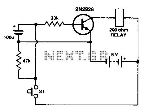
Press SI. The 100 µF electrolytic capacitor rapidly charges up from approximately 0 V. The transistor becomes forward biased, allowing collector current to flow and operate the relay. When SI is released, the capacitor discharges through the 33 K...
The QAMI5516 is an integrated demodulator and decoder solution designed for digital cable receivers, capable of handling compressed video, audio, and data services. This QAM demodulator executes intermediate frequency (IF) to MPEG-2 block processing of QAM carriers. The resulting...
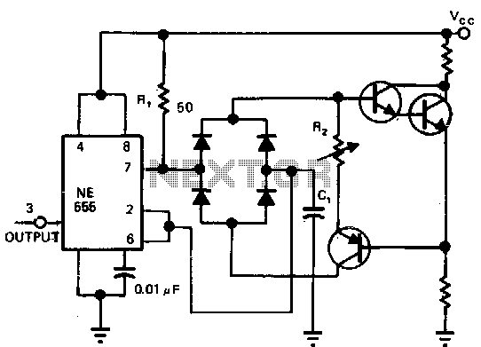
Utilizing a single current source for both the charge and discharge paths in this circuit guarantees that the rise and fall times at the capacitor terminal are identical. A Darlington pair is employed to ensure consistent biasing of the...
A small circuit designed for various time measurement applications. It features an audible sound signal from the buzzer BZ1 and has the capability to drive an external circuit through the optocoupler IC2, once the appropriate circuit is connected to...
This is a programmable clock timer circuit that utilizes individual LEDs to indicate hours and minutes. Twelve LEDs can be arranged in a circle to represent the 12 hours of a clock face, and an additional 12 LEDs can...
This universal triac controller circuit with optocoupler addresses the issue that triacs face when operating at low temperatures, as they require a higher gate trigger voltage. The universal triac controller circuit is designed to enhance the performance of triacs, particularly...