
Unregulated Power Supply

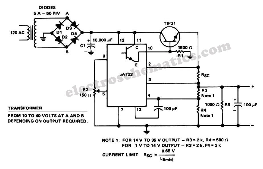
The described full wave rectified power supply circuit employs a transformer, a rectifier, and filtering components to convert alternating current (AC) to direct current (DC). In this configuration, the transformer steps down the input AC voltage to a desired lower voltage level suitable for the load. For instance, a transformer rated at 12V and 1A is appropriate for a load requiring 12V at 1A. However, to ensure reliability and longevity of the power supply, it is prudent to select a transformer with a higher current rating, ideally 1.5A to 2A, to accommodate potential load variations and prevent overheating.
The rectification process in a full wave rectifier typically utilizes either a bridge rectifier configuration or a center-tapped transformer with two diodes. The bridge rectifier consists of four diodes arranged in a bridge configuration, allowing both halves of the AC waveform to contribute to the output DC voltage. This arrangement is beneficial as it maximizes the efficiency of the rectification process by utilizing the entire input waveform, resulting in a smoother DC output.
After rectification, a filtering stage is often implemented to reduce the ripple voltage present in the output. This is commonly achieved using capacitors, which store charge and release it to smooth out fluctuations in the output voltage. The capacitor value is determined based on the load current and the acceptable ripple voltage; larger capacitance values will yield lower ripple but may increase the physical size and cost of the power supply.
Finally, a voltage regulation stage may be included to maintain a stable output voltage under varying load conditions. This can be achieved through linear voltage regulators or switching regulators, depending on the application requirements, efficiency considerations, and thermal management.
Overall, careful selection of components and consideration for worst-case scenarios are essential in designing a robust full wave rectified power supply that meets the needs of the intended electronic application.A basic full wave rectified power supply is shown below. The transformer is chosen according to the desired load. For example, if the load requires 12V at 1amp current, then a 12V, 1 amp rated transformer would do. However, when designing power supplies or most electronic circuits, you should always plan for a worst case scenario. With this in mind, for a load current of 1 amp a wise choice would be a transformer with a secondary current rating of 1.5 amp or even 2 amps.
Allowing for a load of 50% higher than the needed value is a good rule of thumb. 🔗 External reference
Related Circuits
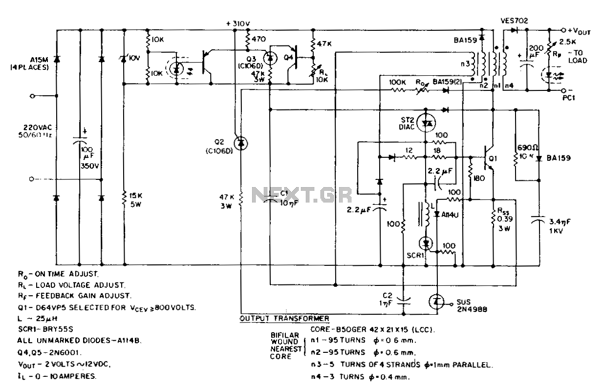
This low-voltage, high-current output switching power supply operates from a 220-V AC input. The circuit employs an ST2 diac relaxation oscillator, Q3, C1, and the diac to initiate conduction of the output switching transistor Q1. The on-time of Q1...
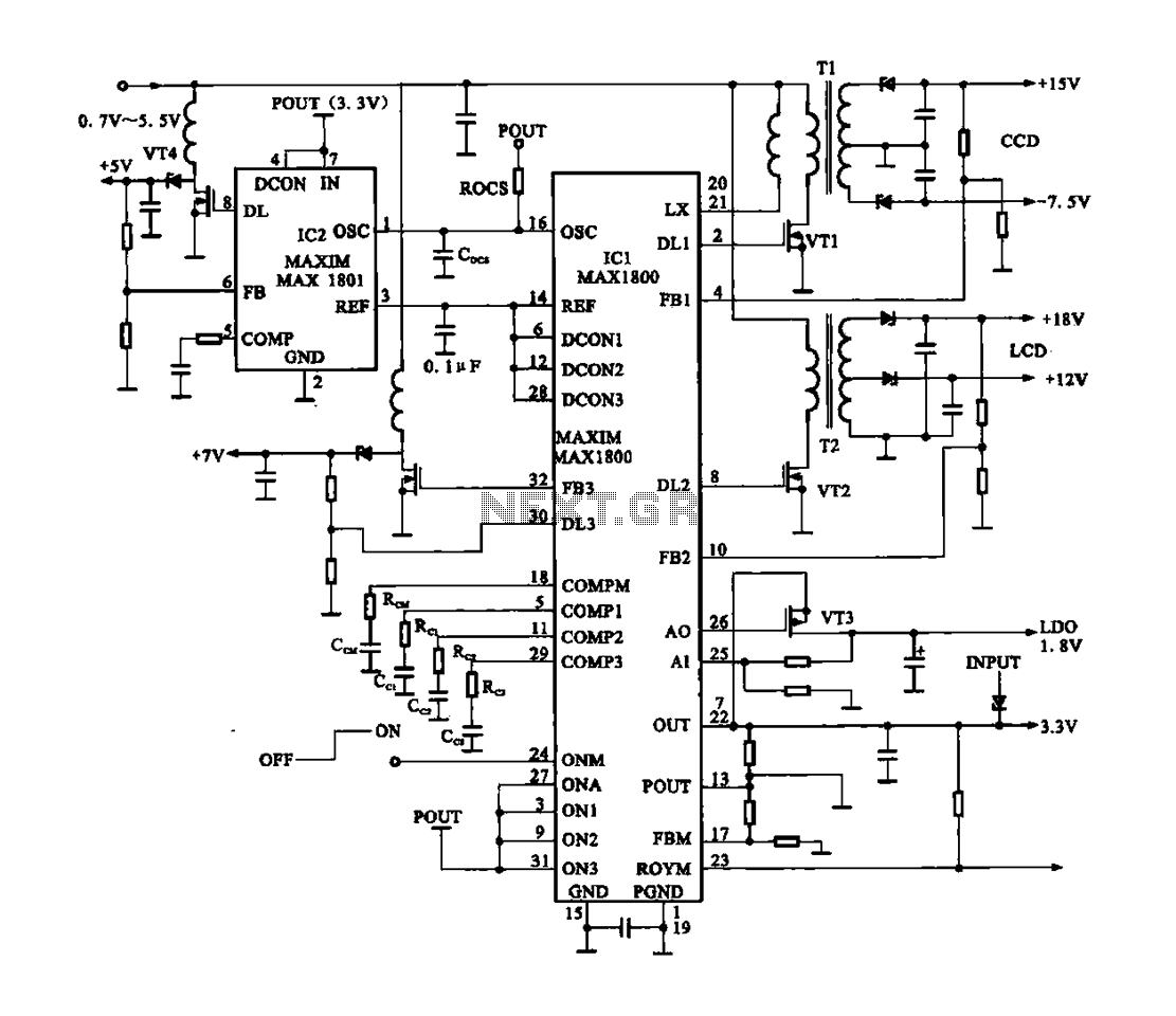
Digital Cameras - DV machine power supply circuit. This circuit utilizes the MAX1800 chip to manage the power supply for digital cameras and DV machines. Digital cameras are typically battery-operated and require low voltages ranging from 0.7 to 5.5...
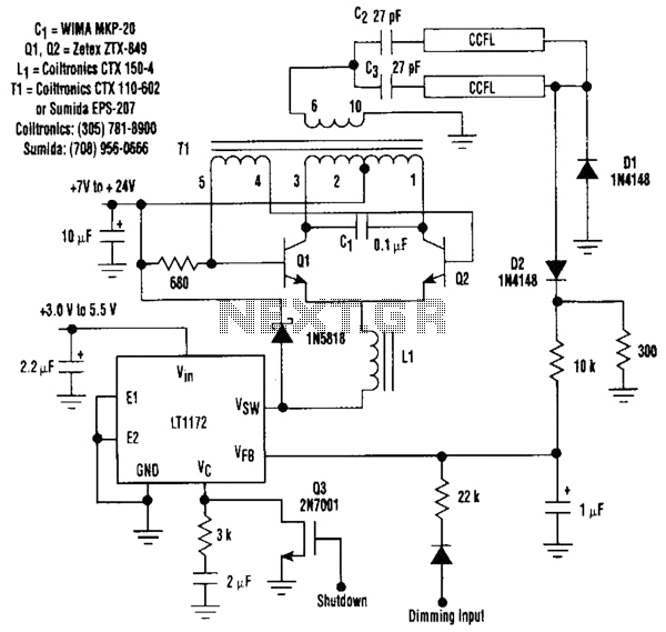
This circuit is a 92%-efficient power supply for cold-cathode fluorescent lamps (CCFLs), which are used to backlight LCDs in portable equipment. The efficiency depends heavily on the component types, particularly C1, Q1, Q2, L1, and T1, whose manufacturers are...

This circuit can supply power to devices that require less than 100mA without any issues. However, it poses a risk of electrical shock and should not be used in applications where users may come into contact with the circuit....
The diagram illustrates the circuit of a versatile USB power socket that safely converts 12V battery voltage into a stable 5V output. This circuit enables the use of various USB-powered devices. The circuit design consists of several key components to...
As the global community becomes increasingly focused on conserving electric power and the fuels that generate electricity, there is a rising demand for products that assist homeowners in monitoring and reducing their power usage. Organizations like Energy Star aim...