
Digital Cameras -DV machine power supply circuit

The power supply circuit for digital cameras and DV machines is designed to efficiently convert low battery voltages into the higher voltages required by the camera's internal components. The MAX1800 chip is central to this operation, utilizing Pulse Width Modulation (PWM) to control the switching of a transformer. This method allows for the generation of multiple output voltages, which are essential for powering various parts of the camera, such as the image sensor, processing unit, and display.
The circuit begins with the battery supplying a low voltage, which is fed into the MAX1800. This chip regulates the input and generates PWM signals that control the operation of the transformer. The transformer steps up the voltage to the required levels through a process of inductive boosting. The outputs of the transformer are then rectified and filtered to provide stable DC voltages of +18 V, +15 V, +12 V, -7.5 V, +1.8 V, and +3.3 V.
The design of this power supply circuit emphasizes efficiency and reliability, ensuring that the digital camera can operate effectively under varying conditions. The inclusion of multiple output voltages allows for versatile application in different camera models and configurations. Additionally, the recommended output voltage from IC2 is crucial for maintaining optimal performance and preventing damage to sensitive components. Overall, this circuit exemplifies the integration of advanced power management techniques in modern digital devices.Digital Cameras -DV machine power supply circuit It shows a digital camera/DV machine power supply circuit, the circuit MAX1800 chip to control the core. The figure shows that digital cameras are battery-powered. Low voltage (0.7 ~ 5.5 V). But the circuit inside a digital camera often requires a higher voltage, such as +18 V, + 15 V, + 1V and the like. To this end the use of digital cameras MAX1800 Li iJ chip PWM signal, and by boosting the way open after two off pulses via a switch transformer (TI, T2) output + 18V, + 15V, + 12V, -7.5V, also outputs + 1.8V and 3.3V DC voltage.
At the same time recommended by the IC2 +V output voltage.
Related Circuits
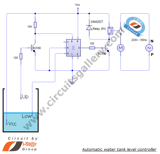
The automatic water level controller circuit is a straightforward engineering project that can automatically switch a domestic water pump on and off based on the water level in a tank. This motor driver circuit can be implemented at home...
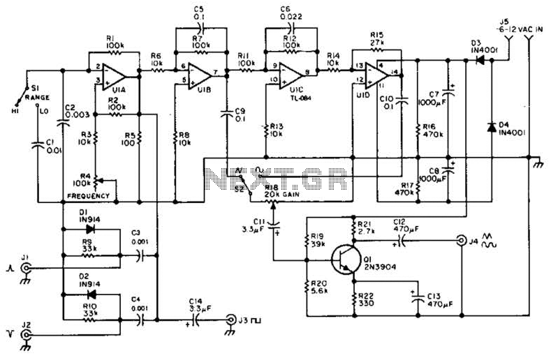
A quad op-amp serves as the core component of this function generator. U1A produces a square wave, which is outputted to J8. J1 and J2 are pulse outputs derived from differentiating the square wave. The integrator U1B creates a...
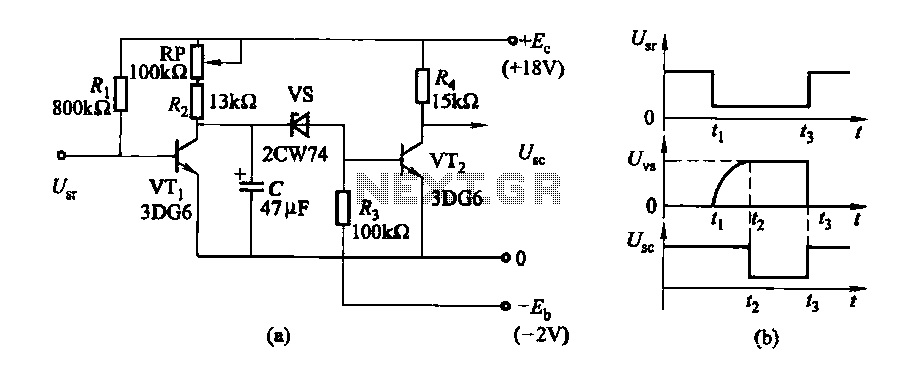
The delay time ranges from 0.5 to 3.5 seconds, which can be adjusted using the potentiometer RP to modify the delay duration. The circuit utilizes a timing mechanism that allows for the adjustment of delay intervals between 0.5 seconds and...

This circuit is used for a Digital Radar Speedometer. It allows for the measurement of the speed of any moving object, particularly vehicles such as cars. The speed is displayed in kilometers per hour (KPH) with a three-digit display....
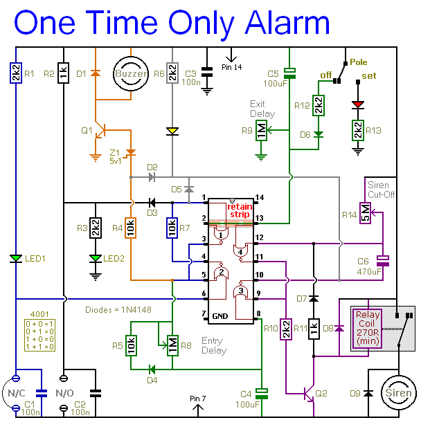
This alarm is designed to activate its siren only once. When the alarm is triggered, the siren will sound for a predetermined duration before automatically turning off and remaining inactive. The alarm system features a single zone with independently...
This tremolo effect circuit utilizes the XR2206 and TCA730 integrated circuits, designed for electronic balance and volume regulation with frequency correction. The circuit is beneficial for stereo channels and can simulate the Lesley effect, also known as the rotating...