
µP-Controlled Oscillator Delivers Rock-Bottom Distortion

The described circuit provides a robust solution for generating low-distortion sinewave outputs suitable for a variety of applications in electronic design and testing. The use of a dual-filter building block allows for precise frequency control, while the tracking notch filter ensures that unwanted harmonics do not affect the output quality. The buffer amplifier serves to isolate the oscillator from subsequent stages, maintaining signal integrity. The integration of a bus-controlled clock generator allows for flexible interfacing with microcontrollers or other digital systems, facilitating easy integration into larger electronic systems. The option to modify the circuit for quadrature outputs enhances its versatility, making it suitable for applications such as phase modulation and signal processing. Overall, this bus-controlled sinewave oscillator design exemplifies a cost-effective approach to generating high-quality sinusoidal signals with minimal distortion.Function generators often play a critical role in the design, testing, and operation of encoders, modulators, demodulators, and measurement instruments. Here`s an inexpensive way to build a bus-controlled sinewave oscillator that has downright low distortion.
The circuit generates a sinusoidal output with typical second and third harmonics down fr om the fundamental by -76. 1 and -74. 2 dB, respectively, across its full output range of 10 Hz to 10 kHz. That performance represents better than a 40-dB improvement over common diode-shaped sinewave generators, which employ a diode-shaping technique to transform a square wave into a sinewave. Typically, their second-and third-order harmonics are down from the fundamental by -35 and -25. 5 dB, respectively. The circuit consists of four sections ( see the figure ). At the heart of the design, the first one is the oscillator comprising an IC dual-filter building block (U1), a second-order clocked filter (whose bandpass-filter section sets the oscillator`s frequency), and a comparator (U2A).
The bandpass filter determines the oscillator`s frequency by allowing signals only around its center frequency to pass. Equation 1 shows the oscillator frequency, and Equation 2 the filter The second circuit section is the tracking notch filter, which is set to and tracks the oscillator`s third harmonic, which is the higher-amplitude harmonic.
The tracking filter is synchronously clocked with the oscillator`s frequency-setting filter to provide lock-step oscillator-tracking filter-response characteristics. The third section has a buffer amplifier (U3A) with a gain of -1. This section includes a 13. 3-kHz low-pass filter to reduce the high-frequency component generated by the clocking steps in the output waveform.
The fourth section is a bus-controlled clock generator that mainly comprises an IC serial-port programmable oscillator (U4), which can be either the LTC6903 for the serial peripheral interface (SPI) or the LTC6904 for the Inter-IC (I2C) interface. Some pull-up resistors, a decoupling capacitor, and a resistor in series with the output are the only external components required.
Plus, the circuit can be modified easily to produce a quadrature, sine/cosine-waveform output. Just add a second output op amp and take its input from the bandpass output of U1 (BPB at pin 11). 🔗 External reference
Related Circuits
The VNGBOX microcontroller must generate a precise, high-resolution, and low-noise DC control voltage to accurately steer the reference oscillator phase. Any noise on this signal can introduce noise to the reference, and any non-linearity, particularly unexpected steps in the...
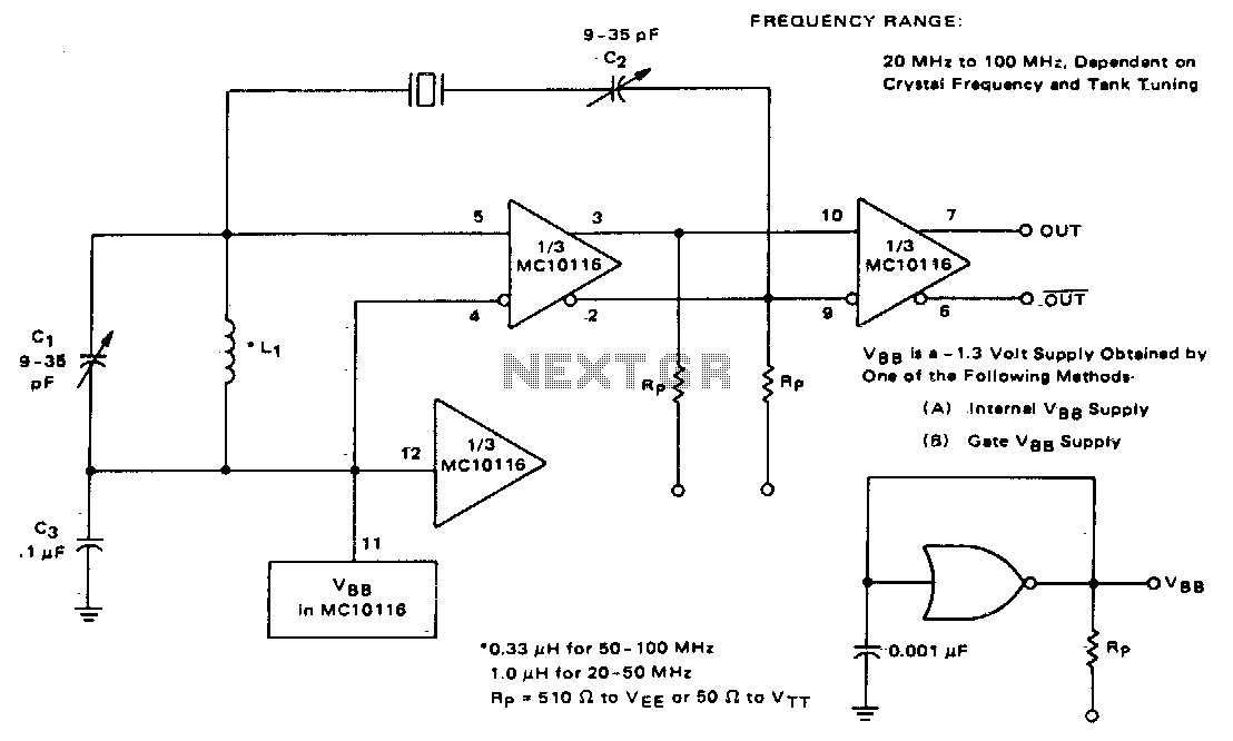
This circuit utilizes an adjustable resonant tank circuit that ensures operation at the desired crystal overtone. Capacitor C1 and inductor L1 form the resonant tank circuit, which can be adjusted to achieve a resonant frequency ranging from approximately 50...
The circuit is based on a simple inductor-capacitor filter circuit, and needs only a pot and a small light bulb to set and stabilise the oscillation. The frequency is fixed, and with a good inductor should be capable of...
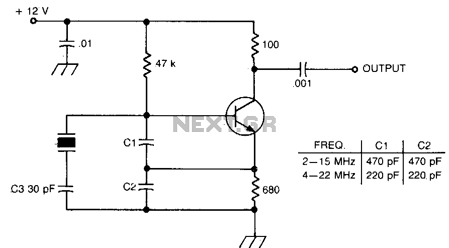
International Crystal OF-1 LO oscillator circuit for fundamental-mode crystals that you can find. The International Crystal OF-1 local oscillator (LO) circuit is designed to operate with fundamental-mode crystals, which are widely used in various frequency generation applications. This oscillator circuit...
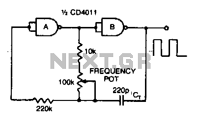
Adjusting the 100 K ohm potentiometer modifies the discharge rate of capacitor Ct, thereby affecting the output frequency. A square wave output is produced. The maximum frequency achievable with CMOS technology is constrained to 2 MHz. The circuit described involves...
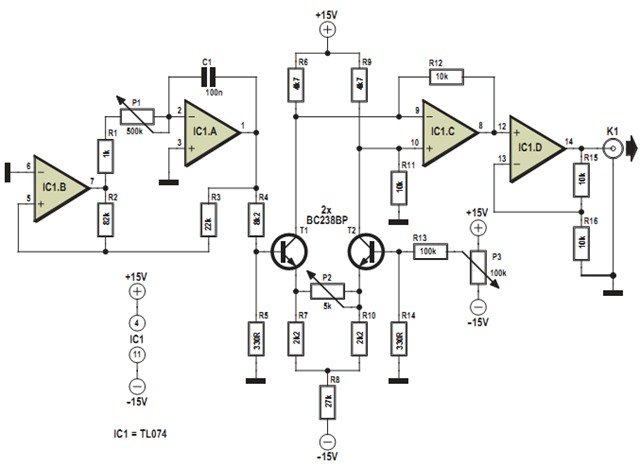
This design was developed to partially replace the well-known 8038 chip, which is no longer in production and therefore difficult to obtain. An existing design for driving a Linear Variable Differential Transformer (LVDT) sensor utilized the 8038 as a...