
Cmos oscillator

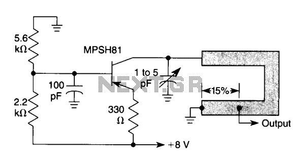
The circuit described involves a timing configuration where a capacitor (Ct) is discharged through a variable resistor (100 K ohm potentiometer). This setup is typically used in oscillator circuits to generate square wave signals. The frequency of the output square wave is inversely related to the discharge time of the capacitor; as the resistance of the potentiometer is increased, the discharge rate of the capacitor decreases, leading to a lower frequency output. Conversely, reducing the resistance allows for a quicker discharge, resulting in a higher frequency.
In a CMOS (Complementary Metal-Oxide-Semiconductor) implementation, the maximum frequency output is limited to 2 MHz due to the inherent switching speed of the CMOS transistors and the time constants associated with the RC (resistor-capacitor) network formed by the potentiometer and the capacitor. The design must consider these limitations to ensure reliable operation within the specified frequency range.
For practical applications, the circuit can be utilized in various timing and waveform generation scenarios, such as clock signals for digital circuits, tone generation in audio applications, or as part of a more complex modulation scheme. Proper selection of the capacitor value and the potentiometer's resistance range will allow for fine-tuning of the frequency output to meet specific application requirements.Varying the 100 K pot changes the discharge rate of Ct and hence the frequency. A square wave output is generated The maximum frequency using CMOS is limited to 2 MHz.
Related Circuits
This result places the oscillator within the UK FM Band, which ranges from 87.5 to 108 MHz. If L1 is equipped with an adjustable ferrite core, its inductance can be modified, allowing for fine tuning. If L1 consists of...
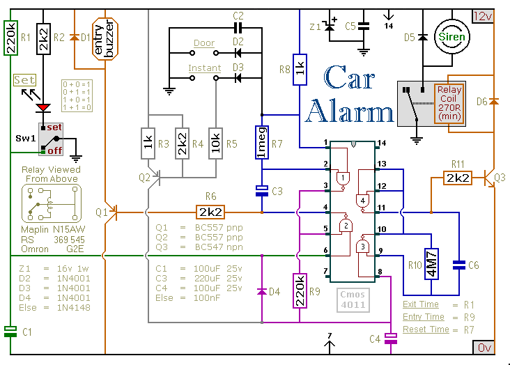
This car alarm circuit includes exit and entry delays, an instant alarm zone, an intermittent siren output, and automatic reset. By incorporating external relays, it is possible to immobilize the vehicle and activate the flashing lights. The car alarm circuit...
A Wien bridge oscillator generates sine waves with a very low distortion level. It produces zero phase shift at a single frequency (f = Vx t RC), which is the oscillation frequency. Stable oscillation can only occur if the...

Examine a traditional Hartley oscillator circuit, and you'll note its trademark: a tapped inductor that determines the frequency of oscillation and provides oscillation-sustaining feedback. Although you can easily calculate the total inductance required for a given frequency, finding the...
This oscillator is typical for operation between 350 to 500 MHz. The microstrip inductor is implemented as a printed circuit board (PCB) trace. The output power ranges from 55 to 100 mW into a 50-ohm load, with frequency stability...
A field effect transistor amplifier features a fixed bias input source with feedback, resulting in very high input impedance and low capacitance. It drives a field effect transistor or emitter follower, despite having a very low output impedance, utilizing...