
USB Blinky

A basic LED circuit can be constructed using a single LED, a current-limiting resistor, and a power source. The LED is a semiconductor device that emits light when current flows through it in the forward direction. The current-limiting resistor is essential to prevent excessive current from damaging the LED.
To build this circuit, the LED's anode (longer lead) is connected to the positive terminal of the power source, while the cathode (shorter lead) is connected to one end of the resistor. The other end of the resistor is then connected to the negative terminal of the power source, completing the circuit.
The value of the current-limiting resistor can be calculated using Ohm's Law. For example, if the power source is 9V and the LED forward voltage is 2V with a desired forward current of 20mA, the resistor value can be calculated as follows:
1. Calculate the voltage across the resistor:
V_R = V_source - V_LED = 9V - 2V = 7V.
2. Use Ohm's Law to find the resistance:
R = V_R / I = 7V / 0.020A = 350 ohms.
A standard resistor value of 360 ohms can be used in this case. This simple LED circuit can serve as a fundamental building block for more complex designs, allowing for the exploration of various configurations and functionalities, such as blinking or fading effects when paired with a microcontroller.My projects typically involve many LEDs and microcontrollers. However sometimes I just love the simplest of things with LEDs. One of the very basic L.. 🔗 External reference
Related Circuits

This document serves as a resource for developers who are new to Texas Instruments (TI) ARM-based processors, as well as for seasoned developers seeking to deepen their understanding of the different ARM architectures. It starts with an overview of...

The core of this construction is 16-Bit Stereo Digital-To-Analog Converter with USB interface PCM2702. PCM2702 needs only a few additional parts to work. The schematic is not complex. The sound card can be powered directly from the USB port...
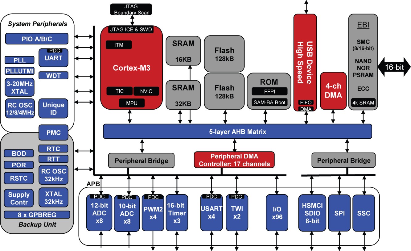
Atmel has joined NXP, ST, Luminary Micro (now TI), and Toshiba as a microcontroller vendor utilizing the ARM Cortex-M3 processor core. The company's initial Cortex-M3 aims to stand out by providing high-speed USB functionality, firmware protection, differential input ADC,...
Problems can arise with USB hubs powered from a PC when devices connected to them draw excessive current. This situation often occurs with devices that use USB cables that are either too long or too thin, leading to voltage...

Daylight shutoff; the schematic has been updated but is not shown here. The daylight shutoff circuit is designed to automatically turn off lighting systems during daylight hours, thereby conserving energy and extending the lifespan of the lighting fixtures. Typically, this...
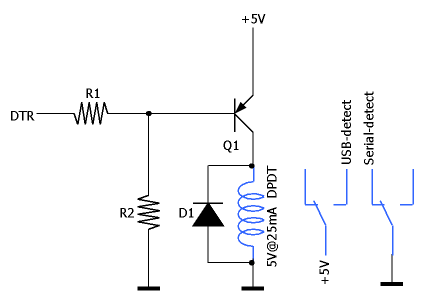
To ensure that the USB and serial segments are electrically isolated, an optocoupler (U1) is employed. The LED section of U1 is directly driven by the Data Terminal Ready (DTR) signal, necessitating the selection of a highly sensitive optocoupler...