
USB IR Toy

The 28pin PIC 18F2550 with USB is back in IR Toy v2. This chip is used in lots of hobby projects that need USB, but it`s starting to show its age. 5volt parts like the 18F2550 are increasing in price, while the 3. 3volt versions with more features (18F25J50) keep getting cheaper. The PIC18F2550 has gone up about $1 since we started v1, it accounts for about 50% of the price increase in v2. Everything runs at 5volts, so power is taken directly from the USB port without regulation. A single power supply pin gets a 0. 1uF decoupling capacitor (C1). The USB features require a 20MHz external oscillator (Q1, C5, C6). The chip is initially programmed thorough a 5pin ICSP header. A 10K pull-up resistor (R1) and a diode (D1) on the MCLR pin protect the rest of the circuit from the 13volt signal used during programming.
The USB transceiver has an internal 3. 3volt regulator that requires a 220nF (0. 22uF) external capacitor (C2). The extra capacitor footprint to use with 0. 1uF capacitors was removed. An infrared demodulator (RX1) decodes infrared remote control transmissions. The demodulator looks for a signal on a carrier wave and decodes it to a clean stream of 1s and 0s. Learn more about infrared modulation and demodulation. We used a demodulator centered at 38kHz, but it will work over a larger range of frequencies at a reduced distance. An alternative demodulator may be needed for 56kHz remote controls. The demodulator connects to a PIC pin with an edge selectable interrupt (RB2/INT2) so we can detect the start of IR activity.
RB2 has a Schmidt trigger to `clean up` a noisy signal. The RX output is also connected to one of the interrupt-on-change pins (RB4) if you want to experiment with a different interrupt type and a TTL pin buffer. While 36-38kHz is the most common frequency for remote controls, some operate at 56kHz, or even more exotic frequencies.
The new infrared frequency detector (RX2) measures raw infrared signals. This is different than the demodulator above. The demodulator looks for a signal on a 38kHz carrier wave and decodes it to a clean stream of 1s and 0s. The detector sees the individual transitions of the carrier wave. The extra sensor data can be used to measure the carrier frequency. It might also be possible to record signals in frequency ranges that don`t work with the 38kHz demodulator.
Working with the detector will show you why remote controls use modulated signals. Any outside noise will degrade the signal quality a lot. A nearby window on a sunny day will activate it. Use it in a dim room and hold the IR source very close (1-2cm) for best results. An infrared LED or emitter (TX) is used to transmit signals. It`s like any other LED, but the color centered around 940nm outside the visible spectrum. The transmitter is connected to a PIC pin with a hardware pulse-width modulator. The PWM makes it easy to create infrared pulses at frequencies visible to IR receivers. IR Toy v2 uses a new constant current driver circuit to power the LED at high currents. It`s way better than the single resistor in the older IR Toy designs. The LEDs get a constant 100mA of current no matter the supply voltage. The USB power supply varies between 4. 5 and 5. 5volts, the new design ensures maximum current at all voltages. More importantly, we don`t rely on a huge current limiting resistor. Previous designs burned excess current in the typical LED current limiting resistor circuit. The resistor needs a minimum power rating of 0. 34watts for 100mA IR LED, way out of the range of common surface mount resistors (<0. 125watts). The constant current driver doesn`t rely on the current limiting resistor nearly as much. High currents are possible using standard SMD parts, but just in case we used a beefy 1206 resistor. IR emitters are typically rated for 100mA of continuous power. Most remote control protocols blink the LED rapidly (modulate it) at around 38KHz, so it is actually off half the time. In this setup many LEDs are rated for double the continuous power rating (200mA). Some are also rated for 1A+, but only for tiny pulses at 50% duty cycle. The IR Toy v2 emitter is limited to the maximum continuous rated current for the IR diode (100mA). Damage is less likely to happen if the transmitter is ever stuck on. It`s a development platform after all, so safety first. You can set your own current by replacing R4 with a smaller value resistor. On the down side we transferred a lot of the current from the resistor to the transistor. The transistor in IR Toy v2 can potentially run hotter than the transistor in v1. For an IR LED with a forward voltage (Vf) of 1. 35 volts the power dissipation is 0. 295W, nearly the rated 0. 310W of the BC818 transistor in an SOT-23 package. This is probably fine because we`re calculating the worst case scenario of a continues 100mA load, IR transmissions are likely to be short and at a 50% duty cycle.
These calculations are also in a spreadsheet in the hardware folder of the project archive. Special thanks to Rafa and rsdio who helped with the constant current circuit. The ICSP group is used to program the PIC. Place a jumper between PGC and PGD to trigger the bootloader. This header was flipped in V2 so the PICKIT2`s extra pin doesn`t interfere with the breakout area. The PIC 18F2550 has an internal 3. 3volt regulator to supply the USB stuff. That regulator must put out a bit of heat because the smallest 18F2550 is in a huge SOIC package. Passive components were changed to 0603 so the board would stay about the same size as v1, despite several extra parts. 0603 isn`t for beginners, but the DO323 diodes are the worst part to solder in our opinion. Neither the PCB nor the diode have much to solder onto. We used the Microchip USB stack to run the 18F2550 as a virtual serial port. Microchip`s code is open but not redistributable. If you want to compile the source, download the stack from Microchip, then drag the source code into the install directory.
See the detailed instructions in the PIC compiler how-to. The QSE159 sensor and rising cost of PIC 18F2550 chips increased the price of IR Toy v2 by more than $2. We`ll try to get the cost back down by using a cheaper 3. 3volt PIC 18F25J50 in v3. 🔗 External reference
Related Circuits
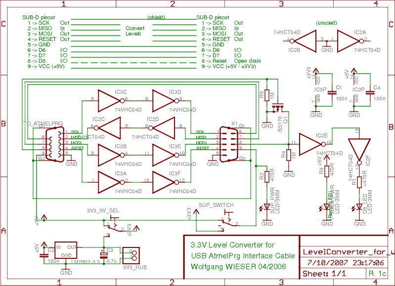
To program devices operating at 3.3V, such as SPI-based AVRs or JTAG-based CPLDs, level conversion is necessary for input and output signal levels. A 5V input may not register as HIGH at 3.3V, and a 3.3V device can be...
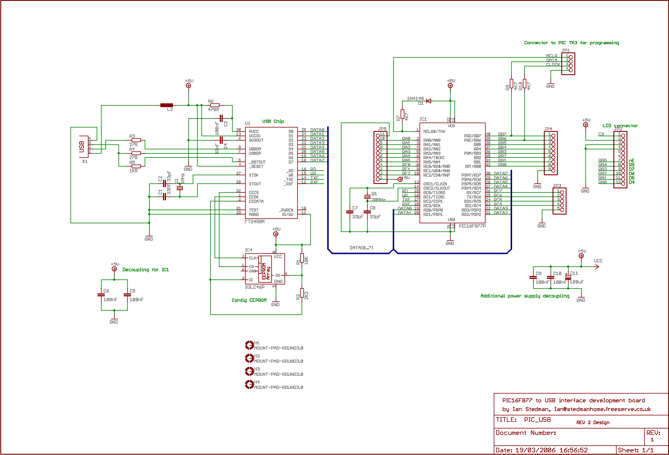
The second program sends "Hello world" to the PC. By default, the board utilizes the Virtual COM Port (VCP) driver, allowing output to be viewed using Hyperterminal or similar software; PuTTY is recommended. The setup is straightforward: upon connecting...
The charger in this project is designed to charge two AA NiMH or NiCd cells of any capacity (as long as they are the same) at approximately 470mA. It will charge 700mAh NiCd cells in about 1.5 hours, 1500mAh...
The light from a flashlight is directed at a phototube, which activates a CMOS logic circuit powered by a battery. This circuit controls the switching action to turn the motor of a model train or other electric toys on...

Illuminate your tabletop with this stylish White LED Lamp. It is powered through a USB port, making it perfect for taking notes while browsing the internet. The USB port can provide a convenient power source. The White LED Lamp is...
Without a USB to phone battery charger circuit, charging a phone battery using a USB port on a computer can quickly damage the battery, resulting in bulging. This occurs because the voltage output from USB is 5 volts, while...