
USB Operated Home Appliances

The described circuit operates as a USB-controlled power switch for various electronic devices, allowing them to be turned on or off in conjunction with a computer. The circuit utilizes a MOC3043 opto-isolator, which is essential for providing electrical isolation between the low-voltage USB side and the high-voltage AC mains side. The zero-crossing detection feature of the MOC3043 is crucial for minimizing electromagnetic interference (EMI) when switching the TRIAC, as it ensures that the TRIAC is activated precisely at the moment when the AC waveform crosses zero volts.
The BT126 TRIAC is capable of handling substantial current loads, making it suitable for controlling devices such as printers and other peripherals that may draw significant power. The inclusion of a 1-A fuse serves as a protective measure, preventing damage to the circuit in the event of an overload or short circuit. For applications involving larger loads, it is recommended to select a fuse with a higher current rating to accommodate the increased power demand.
In scenarios where inductive loads are present, such as motors or transformers, a snubber network—typically composed of a resistor and capacitor in series—should be placed across the TRIAC. This network helps to suppress voltage spikes generated by the inductive load, which could otherwise damage the TRIAC and compromise the circuit's reliability.
Integration into a mains multi-way powerboard is straightforward, allowing for multiple devices to be controlled simultaneously. However, it is imperative to maintain adequate isolation between the USB circuitry and the mains voltage to ensure user safety and compliance with electrical standards. This can be achieved through careful design and layout, ensuring that no conductive paths exist between the two sections of the circuit.When turning a computer on and off, various peripherals (such as printers, screen, scanner, etc. ) often have to be turned on and off as well. By using the 5-V supply voltage from the USB interface on the PC, all these peripherals can easily be switched on and off at the same time as the PC. This principle can also be used with other appliances tha t have a USB interface (such as modern TVs and radios). This so-called USB-standby-killer` can be realized with just 5 components. The USB output voltage provides for the activation of the triac opto-driver (MOC3043) which has zero-crossing detection. This, in turn, drives the TRIAC, type BT126. The circuit shown is used by the author for switching loads with a total power of about 150 W and is protected with a 1-A fuse.
The circuit can easily handle much larger loads however. In that case and/or when using a very inductive load a so-called snubber network is required across the triac. The value of the fuse will also need to be changed as appropriate. The circuit can easily be built into a mains multi-way powerboard. Make sure you have good isolation between the USB and mains sections. 🔗 External reference
Related Circuits

We are OUT OF STOCK on the surplus brushless DC motor we used to build this project, and since it's surplus we cannot get any more. The resistor and capacitor values listed in the schematic and on the PC...
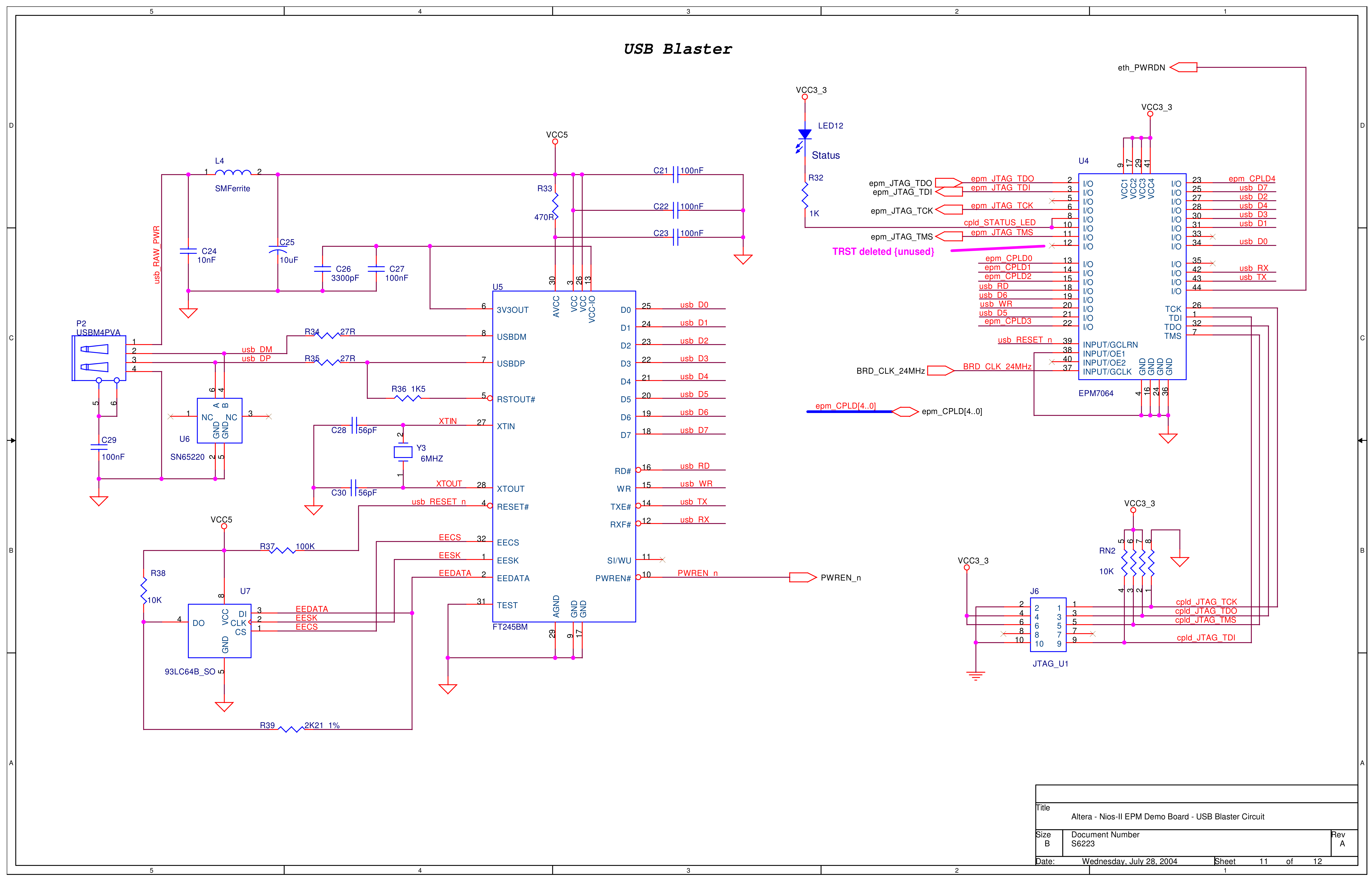
The Altera USB-Blaster is an effective USB JTAG programmer, with clones available for US$10 or less. It includes a detailed manual that features a pinout diagram for the JTAG device side. However, the diagram lacks orientation details. A polarization...

The generator output is rectified, filtered, and applied between the positive supply voltage and the base of the detector transistor. This configuration provides a negative voltage that reduces the base voltage as the speed increases. During normal operation, if...

The peripheral circuit is straightforward, consisting of a DAC schematic circuit diagram for a USB interface that utilizes the PCM2702. The output of the circuit can be directly connected to a power amplifier and is capable of driving headphones...

This circuit is designed to produce DMX output for entertainment lighting from a PC. It offers flexibility in circuit configurations. By opting for no isolation, the setup requires only a PIC microcontroller and a standard RS-485 driver, with an...

The circuit operates by sending ringing pulses through capacitor C1, resistor R1, and diode D2 to charge capacitor C2 to a voltage of 6V. This voltage causes transistors N1 and N2 to reverse, which activates V1, the analog hook,...