
Homemade Easter Egg Anemometer

The circuit described relies on a specific surplus brushless DC motor, which is no longer available. The design of the circuit is tailored to the electrical characteristics and operational parameters of this particular motor, including its voltage and current ratings. The resistor and capacitor values specified in the schematic are integral to the performance of the circuit, as they are selected based on the motor's electrical properties.
In a typical brushless DC motor circuit, the motor is driven by a controller that manages the switching of power to the motor phases. The controller typically employs a pulse-width modulation (PWM) technique to regulate speed and torque. The resistors in the circuit may be used for current sensing, feedback, or biasing, while the capacitors could serve to filter noise, stabilize voltage levels, or provide decoupling.
When designing or modifying a circuit that uses a specific motor, it is essential to consider the impact of substituting the motor with a different model. Variations in motor specifications can lead to improper operation, overheating, or failure of components. Therefore, if a replacement motor is required, it is advisable to analyze its characteristics and adjust the resistor and capacitor values accordingly to ensure compatibility with the existing circuit design.
In summary, the circuit's performance is closely tied to the specific brushless DC motor used, and careful consideration must be given to any future implementations or modifications that involve different motor components.We are OUT OF STOCK on the surplus brushless DC motor we used to build this project, and since it`s surplus we cannot get any more. The resistor and capacitor values listed in the schematic and on the PC board plan depend on using this exact same motor.
🔗 External reference
Related Circuits
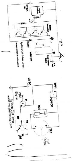
One of the simplest methods to create a battery-powered high-voltage power supply is by utilizing a common car ignition coil. Ignition coils function as a type of induction transformer, inspired by the Tesla Coil invented by Nikola Tesla in...
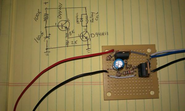
The momentary hold relay board and the accessory delay module are components designed for automotive applications. The momentary hold relay board powers the GPS unit and the tablet, eliminating the need for manual button activation. The accessory delay module...
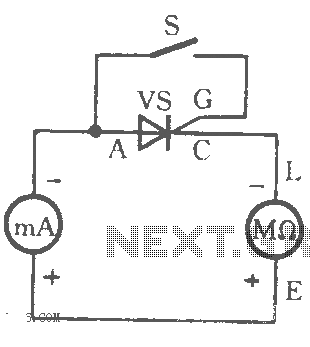
The table illustrates the capability to trigger the thyristor circuit diagram. The thyristor circuit diagram serves as a fundamental component in various electronic applications, particularly in power control and switching. A thyristor is a four-layer semiconductor device that functions as...
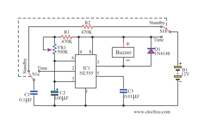
This is a simple and compact timer circuit (Egg Timer) using the IC 555. It features an alarm activated by a buzzer. This mini timer circuit is quite interesting and is referred to as the Egg Timer. The circuit utilizes...
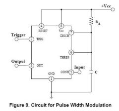
The circuit is effective for controlling the power supplied to devices such as fans, LEDs, or transformers and coils. By adjusting the pulse width, it is possible to control the speed of a fan without compromising torque. The IRF740...
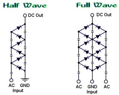
How to create a voltage multiplier using diodes and capacitors, capable of producing extremely high voltage. A voltage multiplier is a circuit that converts a lower AC or DC voltage into a higher DC voltage using a combination of capacitors...