
Altera USB-Blaster plug pinout

The Altera USB-Blaster serves as a vital tool for programming and debugging FPGA devices utilizing the JTAG interface. The device connects to the host computer via a USB interface, enabling straightforward programming of compatible hardware. The USB-Blaster is designed to support a variety of Altera devices, making it a versatile choice for developers and engineers working with programmable logic.
The pinout diagram provided in the manual is essential for users to correctly connect the USB-Blaster to their target device. Each pin in the 10-pin female connector corresponds to specific signals required for JTAG communication. Although the absence of orientation details in the diagram may lead to confusion, it is critical to ensure proper alignment to avoid damage to the device or programmer.
The expected polarization lug on the connector is a common feature in many JTAG programming interfaces, designed to prevent incorrect insertion. Its absence in this design may necessitate careful handling by users to ensure that the connector is aligned correctly during installation. To facilitate proper connections, users are advised to refer to the specifications of their target device and to verify the pin configuration before proceeding with programming.
In summary, the Altera USB-Blaster is a cost-effective solution for JTAG programming, but users should exercise caution regarding the pin orientation and connection integrity to ensure successful operation.The Altera USB-Blaster is an efficient USB JTAG programmer. Clones sell for US$10 or less. The programmer comes with a comprehensive manual with a pinout diagram for the JTAG device side. [1] That diagram unfortunately shows no orientation. There should be a polarisation lug to the 10-pin female plug in figure 2-3, but it isn`t.. 🔗 External reference
Related Circuits
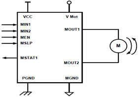
The schematic presented illustrates a 5A H-Bridge Module designed for the operation of a single Bipolar DC motor. The H-Bridge Module includes a header set (J2) and a connector terminal set (J1). Below is the pinout description for the...

Most small internal combustion engines commonly used in model building utilize glow plugs for starting. However, glow plugs operate at a voltage of 1.5 V, while components such as fuel pumps, starter motors, and chargers typically operate at 12...
All errors in circuit diagrams, documents, and layout have been corrected. The circuit shown is functional and operational. It is important to note that Q2 is sensitive and can be easily damaged by incorrect connections, shorts, over-voltage, or excessive...

This device comprises a ring detector connected to the telephone line. When the telephone rings, the ring detector imposes high-frequency pulses on the AC power line. A receiver located anywhere on the same power line detects these pulses and produces...

Pinout of a smart card (SIM card) to PC adapter cable (SIM reader/writer) schematic and layout of a 6-pin SIM card special connector and a 9-pin D-SUB female connector used to connect computers to ISO 7816 compatible chip card...

Most standard household appliances and portable hand tools can be adapted for variable-speed operation using a simple half-wave SCR phase control. This device can serve as the speed control unit for typical loads, provided they utilize series universal (brush...