
usb printer share switch circuit project

The schematic for this USB switcher device incorporates a rotary switch that connects to the USB lines of the device. The rotary switch has multiple positions, each corresponding to one of the two PCs. When the switch is turned, it alters the connection path, allowing either PC to communicate with the shared USB device. The USB device is connected to a common USB port on the switch, which routes the data lines (D+ and D-) and power lines (VCC and GND) appropriately based on the selected position of the rotary switch.
The two LEDs serve as indicators, providing visual feedback on which PC is currently selected. Each LED is connected in parallel with the corresponding output of the rotary switch. When a PC is selected, its associated LED lights up, confirming to the user that the USB device is connected to that particular computer.
Power management is crucial in this design, ensuring that the USB device receives the correct voltage and current from the selected PC. The circuit may include additional components such as resistors for current limiting on the LED indicators and capacitors for smoothing any power fluctuations.
This USB switch can be particularly useful in environments where multiple computers need access to shared peripherals without the need for constant plugging and unplugging of devices, enhancing convenience and efficiency in a multi-computer setup.This simple device allows two computers to share a single USB printer or some other USB device, such as an external flash drive, memory card reader or scanner. A rotary switch selects the PC that you wish to use with the USB device, while two LEDs indicate the selected PC..
🔗 External reference
Related Circuits
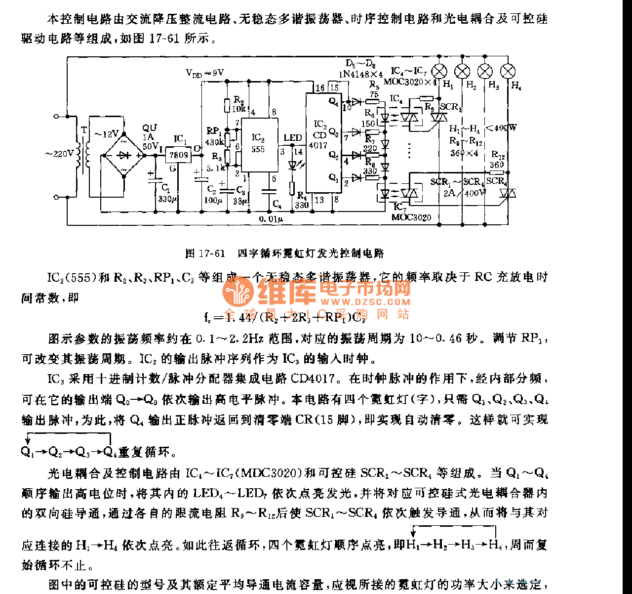
This control circuit consists of an AC step-down rectifier circuit, an astable multivibrator, a timing control circuit, an optocoupler circuit, and an SCR driving circuit, as illustrated in Figure 17-61. The astable multivibrator is formed using IC2 (555), resistors...
This little guide for every electronics tester would actually have to lie in the toolbox. You can have components such as resistors, capacitors, diodes, etc. of testing. T1 and T2 form a Darlington. Therefore only need a small base...
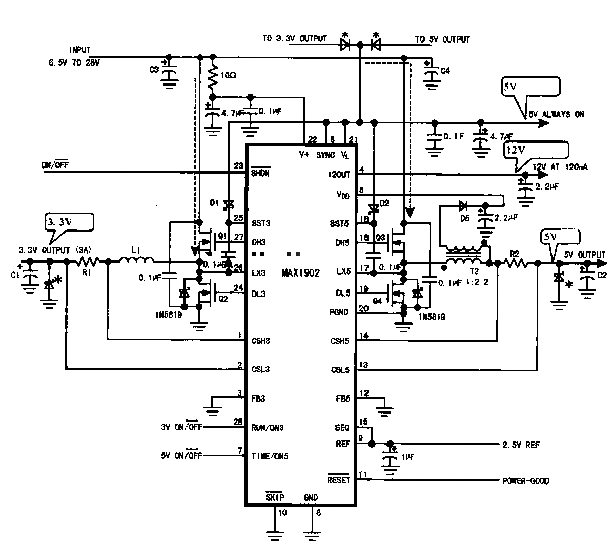
Multi-output power supply circuit (MAX1902). This circuit illustrates the power supply configuration for a notebook computer motherboard, utilizing the MAX1902 chip for power control. It is designed to convert the battery's DC voltage into multiple DC voltage outputs. The multi-output...
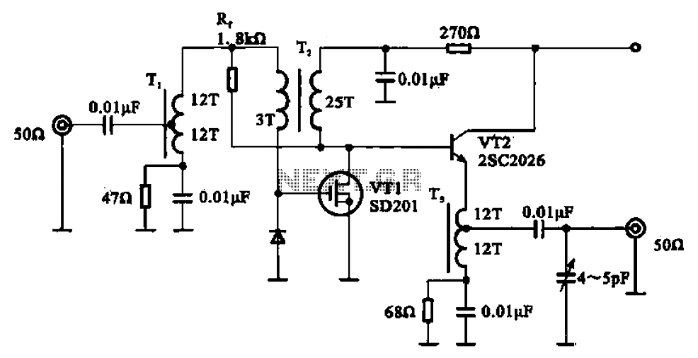
A broadband amplifier circuit utilizing a negative feedback amplifier configuration is presented. This circuit employs transformer coupling and a combination of amplifying sections and field-effect transistors (FETs). The input signal is applied to the center tap of the transformer...
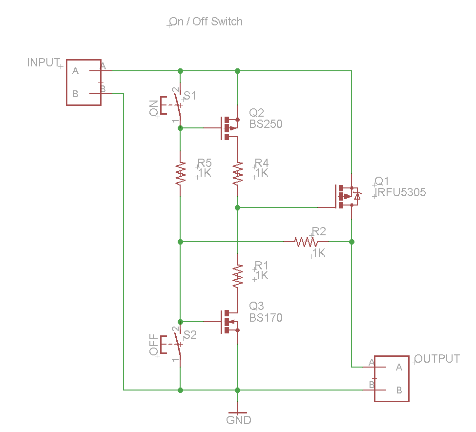
A power button configuration consisting of two buttons, one for turning on and another for turning off. This system is required to switch a voltage of approximately 15 V and a current of up to 10 A for a...
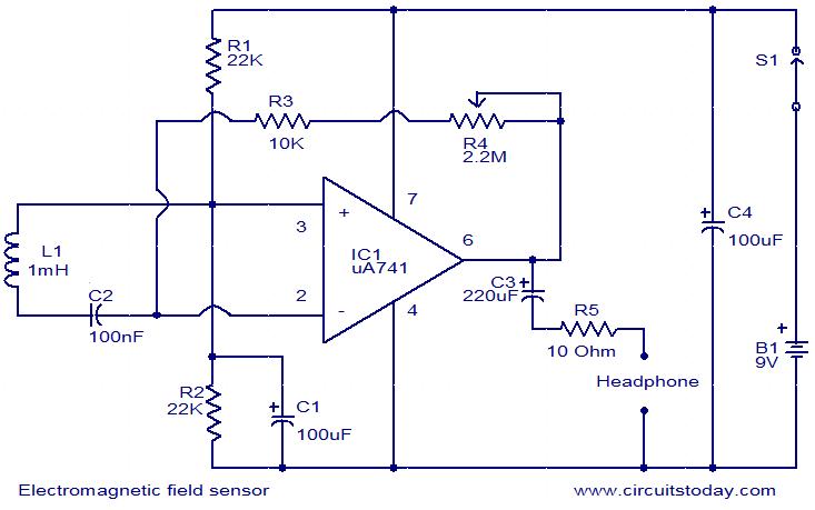
The following circuit illustrates an Electromagnetic Field Sensor Circuit Diagram. This circuit is based on the uA741 integrated circuit. Features: it is used to sense electromagnetic fields. The Electromagnetic Field Sensor Circuit utilizes the uA741 operational amplifier to detect variations...