
USB Powered Mobile Phone Battery Charger

This circuit is designed to deliver a stable 4.7 volts necessary for the optimal charging of mobile phone batteries, which typically require a lower voltage than what is provided by standard USB outputs. The use of a medium power NPN transistor allows for adequate regulation of the voltage, ensuring that the output remains consistent despite variations in input voltage or load conditions.
The Zener diode D2 plays a crucial role in maintaining the desired output voltage by shunting excess voltage away from the load, thereby preventing overcharging and potential damage to the battery. The inclusion of diode D1 is essential for protecting the circuit from reverse polarity connections, which could otherwise lead to circuit failure or damage.
The choice of a Type A USB plug for the front end of the circuit is practical, as it allows for compatibility with a wide range of power sources, including wall chargers and computer USB ports. The specified wiring connections (red to pin 1 and black to pin 4) facilitate straightforward identification of positive and negative terminals, minimizing the risk of incorrect connections during assembly.
For assembly, it is recommended to use a breadboard or a similar prototyping platform to test the circuit before finalizing the design. Once the circuit is assembled, measuring the output voltage with a multimeter will confirm that it is within the desired range. If the voltage is stable and the polarity is correct, the circuit can be safely connected to the mobile phone for charging. This design effectively balances the need for a regulated output with the efficiency of low-current charging, promoting the longevity of lithium-ion or NiMH batteries commonly used in mobile devices.This simple circuit can give regulated 4. 7 volts for charging a mobile phone. USB outlet can give 5 volts DC at 100mA current which is sufficient for the slow charging of mobile phones. Most of the Mobile Phone batteries are rated 3. 6 volts at 1000 to 1300 mAh. These battery packs have 3 NiMh or Lithium cells having 1. 2 volt rating. Usually the ba ttery pack requires 4. 5 volts at 300-500 mA current for fast charging. But low current charging is better to increase the efficiency of the battery. The circuit described here provides 4. 7 regulated voltage and sufficient current for the slow charging of the mobile phone. Transistor Q1 is used to give the regulated output. Any medium power NPN transistor like CL100, BD139, TIP122 can be used. Zener diode D2 controls the output voltage and D1 protects the polarity of the output supply. Front end of the circuit should be connected to a A type USB plug. Connect a red wire to pin1 and black wire to pin 4 of the plug for easy polarity identification. Connect the output to a suitable charger pin to connect it with the mobile phone. After assembling the circuit, insert the USB plug into the socket and measure the output from the circuit. If the output is OK and polarity is correct, connect it with the mobile phone. 🔗 External reference
Related Circuits
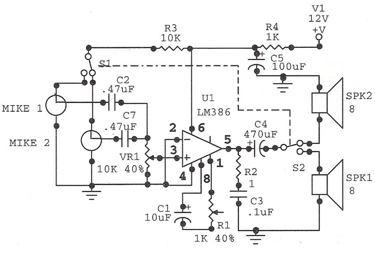
The LM386 is an ideal choice for a door phone application. This device is particularly beneficial in modern urban households, utilizing a condenser microphone and a speaker. The LM386 is a low-voltage audio power amplifier that is commonly used in...
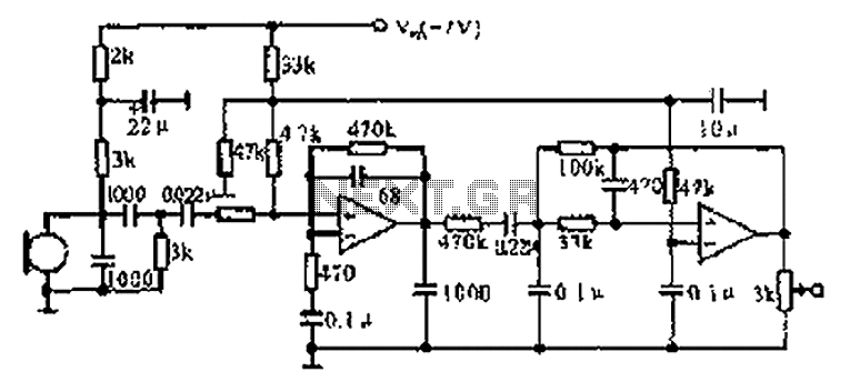
The CX9800 models of mobile phones and desktop PCs feature a high-performance voice processing circuit that compresses the amplitude and bandwidth of the microphone signal. This design enhances the sensitivity of the microphone and its adaptability to varying distances....
This automotive battery charger project is designed to charge 12V electrolyte lead-acid batteries. The automotive battery charger circuit is engineered to efficiently charge 12V lead-acid batteries, which are commonly used in vehicles. The design typically incorporates several key components, including...
The ZSSC1856 from ZMDI Company is a double-channel ADC integrated with an embedded MCU, composed of two chips packaged in a PQFN32 5x5mm format. The system's basic chip, the System Basis Chip (SBC), incorporates high voltage circuits, a LIN...
Power and serial communications are provided by the FTDI USB to RS232 converter chip. No additional setup is required; simply connect the USB cable from the computer to the board, and a new serial COM port will be installed...
Building a headphone amplifier is like building a power amp - only the current demand is just a little bit lower (about a factor 100). Various designs can be found in the internet, and it is relatively easy to...