
Automotive Battery Charger Project

The automotive battery charger circuit is engineered to efficiently charge 12V lead-acid batteries, which are commonly used in vehicles. The design typically incorporates several key components, including a transformer, rectifier, voltage regulator, and various protection circuitry to ensure safe and effective charging.
The transformer steps down the input AC voltage to a lower AC voltage suitable for charging the battery. The output from the transformer is then fed into a rectifier, usually a bridge rectifier configuration, which converts the AC voltage to pulsating DC. This pulsating DC is then smoothed out using filter capacitors to provide a more stable DC output.
To regulate the charging voltage and prevent overcharging, a voltage regulator is implemented. This component ensures that the output voltage remains within the safe charging limits for the lead-acid battery, typically around 14.4 to 14.7 volts for a fully charged state. The regulator may be a linear type or a switching regulator, depending on the efficiency requirements of the design.
Additionally, the circuit may include protection features such as fuses or circuit breakers to prevent overcurrent conditions, as well as thermal protection to guard against overheating. An LED indicator may also be included to provide visual feedback on the charging status, signaling when the battery is charging or fully charged.
Overall, the automotive battery charger circuit is designed to deliver a reliable and safe charging solution for 12V lead-acid batteries, ensuring longevity and optimal performance in automotive applications.This automotive battery charger project is designed to charge 12V electrolyte lead acid batteries. .. 🔗 External reference
Related Circuits
The above circuit can be useful to detect if the load of any battery charger or plug-in adaptor supply is not properly connected. The load can be a set of batteries to be charged or any other type of...
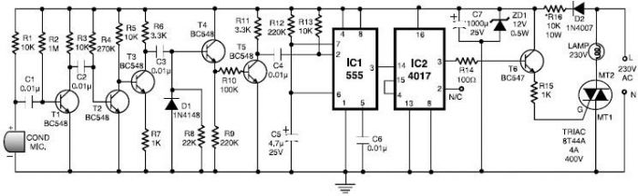
This 555 timer clap switch circuit electronic project is designed using common electronic components. The circuit operates from a distance of up to 10 meters from the microphone. The signal from the microphone is amplified by transistors T1, T2,...
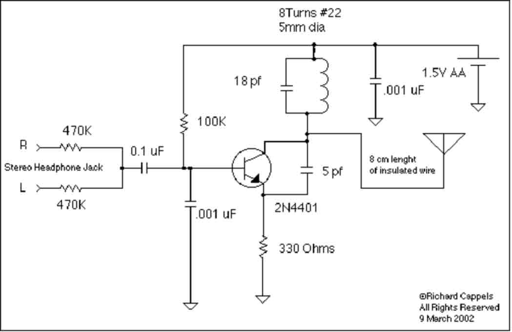
This device is designed to rebroadcast the output of a CD player, television receiver, or radio receiver. It allows for mobility within the home, enabling users to enjoy their favorite programs without being tethered to the source. The effective...
The circuit was constructed on a Vero board and tested with a large electrolytic capacitor in place of a battery. A 500-ohm preset resistor determines the output voltage, while a 47k preset resistor regulates the hysteresis and establishes the...
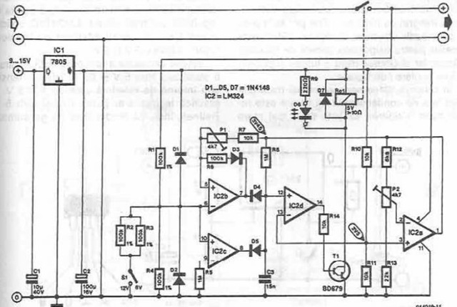
A simple battery charger is designed to disconnect the battery when the charge voltage reaches its nominal level and reconnect when the battery voltage drops below a predefined threshold. This is achieved using a circuit diagram that incorporates a...
Construct a doorbell chime using a 555 timer integrated circuit, a speaker, five resistors, four electrolytic capacitors, one ceramic capacitor, three diodes, a pushbutton switch, and a 9V battery as the power supply. The circuit design for the doorbell chime...