
USB Soundcard Circuit with PCM2702

The PCM2702 is a versatile USB audio controller that integrates a USB interface with a digital-to-analog converter (DAC) and an audio codec. It supports a variety of audio formats and is capable of high-quality sound reproduction. The circuit typically includes a few essential components: the PCM2702 IC, passive components such as resistors and capacitors, and connectors for USB and audio output.
To construct the USB sound card circuit, the PCM2702 is connected to the USB power supply and data lines. The IC manages the audio data received from the USB interface and converts it into an analog signal that can be sent to speakers or headphones. Additional components may include decoupling capacitors to ensure stable power supply, resistors for signal conditioning, and a low-pass filter to eliminate high-frequency noise from the output signal.
The output stage of the circuit can be configured to drive headphones directly or to connect to an external amplifier for driving larger speakers. The design can also incorporate a volume control feature using a potentiometer to adjust the audio output level.
Overall, the PCM2702-based USB sound card circuit is an efficient solution for adding audio capabilities to various electronic projects, providing a simple yet effective way to achieve high-quality sound output.Circuit USB Soundcard Circuit with PCM2702 schematics Circuit Electronics, Creating a sound card is not more complex problems. If you useGreat IC PCM2702 from Burr RED / Texas Instruments you can create a cardUSB sound fully functional.
The.. 🔗 External reference
Related Circuits
The foot 13 between valve value 1 and valve value 2 will draw the transistor base current. If the relay releases, after a recovery time of 0.5 seconds, pressing the key will initiate the switching process again. The timer...
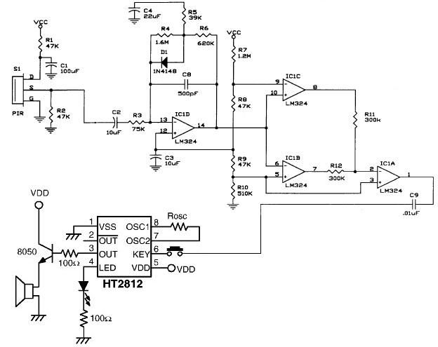
The operational amplifier IC1D modifies the frequency response to enhance the frequencies generated during motion detection while eliminating others, such as noise or gradual temperature variations. When the output voltage of IC1D exceeds 1.67V, it activates pins 8 and...
This project features a schematic for a touch alarm circuit. The circuit is highly sensitive and activates a piezo buzzer or any other type of buzzer, along with an LED, for a predetermined duration when a metal plate is...
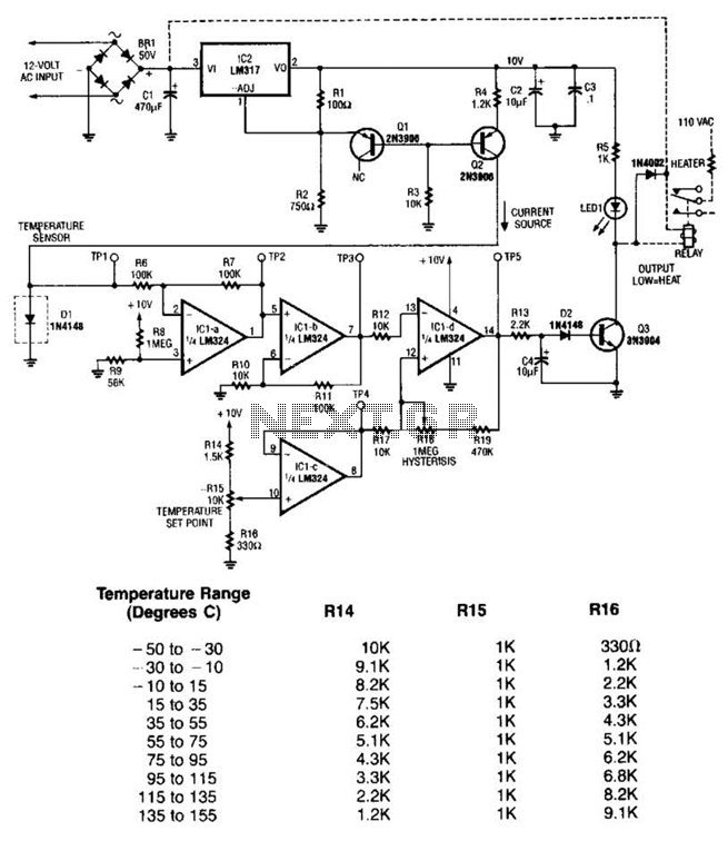
The LM35 temperature sensor outputs 10 mV/C for each degree Celsius above 0°C. At 20°C, the output voltage is calculated as 20 × 10 = 200 mV. The circuit consumes minimal power. Additionally, the load resistance should not be...
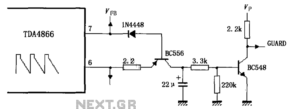
As illustrated in FIG TDA4866, the circuit consists of an external signal generator circuit protection. The internal protection circuit's role is to manage control, while the external protection circuit performs its functions. During normal operation, the vertical amplitude of...
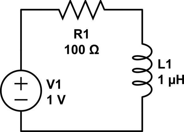
Consider a circuit consisting of a voltage source, a resistor, and an inductor arranged in a closed loop. When the voltage source is activated, the circuit reaches a steady state, during which the inductor stores energy calculated by the...