
USB sound card with PCM2702

More: PCM2702 needs only few additional parts to work. The schematic is not complex. Sound card can be powered directly from USB port (jumper W1) or from external power supply (jumper W3). PCM2702 needs two power supply 3.3V (3V-3.6V) and 5V (4.5V-5.5V). I used fixed output voltage LDO TPS76733Q for 3.3V (IO2) and adjustable output voltage LDO TPS76701Q for 5V (IO3). Both LDO are produced by TI, I used this because I had it in my drawer. Any similar LDO can be used. Output voltage of IO3 should be set to little bit lower than input voltage to allow LDO good stabilization, in my case output voltage is set to 4.8V. Output voltage can be set by adjustable resistor R33. In case of low power supply, IO3 can be shorted by jumper W3. LED D3 signalizes power on.
Small ferrite beads are placed before all power pins of PCM2702 and in Vbus and GND of USB. These small beads reduce high frequency hum. I had a problem find this small SMD ferrite beads in local stores but finally I acquire few of them from old hard drive. They are not absolutely necessary, you can use zero ohm resistors instead of them. During writing this article I have found that PCM2702 is now not recommended for new design, but TI offer even better solution. PCM2704, PCM2705 have same functionality as PCM2702, but they include output filter. They are able to drive directly headphones. Volume and Mute can be controlled through SPI bus in PCM2705 or with pushbuttons in case of PCM2704. PCM2704 and PCM2705 are in TSSOP28 package. PCM2706 is similar to PCM2704 and PCM2707 to PCM2705 but in addition they have I2S bus. PCM2706 and PCM2707 are in TQFP32 package. Low-pass filter is placed in output signal path to reduce sampling frequency. An OPA2353UA dual op amp is configured as a stereo 2nd-order low-pass filter.
Led diode D1 is illuminated when PCM2702 plays audio data received from the USB bus. Led diode D2 is illuminated when USB bus suspends audio data transmission to the PCM2702.
The PCM2702 USB sound card design incorporates several essential components and configurations to ensure effective audio signal processing. The circuit's power supply is derived from the USB port, with the option to use an external power source, providing flexibility in various applications. The use of low-dropout regulators (LDOs) TPS76733Q and TPS76701Q ensures stable voltage levels for the PCM2702, which is critical for maintaining audio quality. The PCB layout should consider the placement of ferrite beads to mitigate high-frequency noise, which can affect audio performance.
The output stage includes a low-pass filter implemented with the OPA2353UA op-amp, which is vital for attenuating high-frequency artifacts introduced during the digital-to-analog conversion process. The design also allows for future upgrades with newer PCM270x series chips, which offer enhanced features like integrated headphone drivers and I2S bus support. The inclusion of indicator LEDs provides visual feedback for operational status, enhancing usability. Overall, this schematic presents a robust solution for creating a USB audio interface suitable for various audio applications while maintaining simplicity in design.If you use great IC PCM2702 from BURR BROWN / Texas Instruments you can create a fully functional USB sound card. This sound card can be powered from USB port and has one stereo output. You don’t need to install any driver for Windows XP and Vista, because they are already inside. This is really plug and play. The core of this construction is 16-Bit Stereo Digital-To-Analog Convertor with USB interface PCM2702.
PCM2702 needs only few additional parts to work. The schematic is not complex. Sound card can be powered directly from USB port (jumper W1) or from external power supply (jumper W3). PCM2702 needs two power supply 3.3V (3V-3.6V) and 5V (4.5V-5.5V). I used fixed output voltage LDO TPS76733Q for 3.3V (IO2) and adjustable output voltage LDO TPS76701Q for 5V (IO3).
Both LDO are produced by TI, I used this because I had it in my drawer. Any similar LDO can be used. Output voltage of IO3 should be set to little bit lower than input voltage to allow LDO good stabilization, in my case output voltage is set to 4.8V. Output voltage can be set by adjustable resistor R33. In case of low power supply, IO3 can be shorted by jumper W3. LED D3 signalizes power on. Small ferrite beads are placed before all power pins of PCM2702 and in Vbus and GND of USB. These small beads reduce high frequency hum. I had a problem find this small SMD ferrite beads in local stores but finally I acquire few of them from old hard drive.
They are not absolutely necessary, you can use zero ohm resistors instead of them. During writing this article I have found that PCM2702 is now not recommended for new design, but TI offer even better solution. PCM2704, PCM2705 have same functionality as PCM2702, but they include output filter. They are able to drive directly headphones. Volume and Mute can be controlled through SPI bus in PCM2705 or with pushbuttons in case of PCM2704. PCM2704 and PCM2705 are in TSSOP28 package. PCM2706 is similar to PCM2704 and PCM2707 to PCM2705 but in addition they have I2S bus. PCM2706 and PCM2707 are in TQFP32 package. Low-pass filter is placed in output signal path to reduce sampling frequency. An OPA2353UA dual op amp is configured as a stereo 2nd-order low-pass filter. Led diode D1 is illuminated when PCM2702 plays audio data received from the USB bus. Led diode D2 is illuminated when USB bus suspends audio data transmission to the PCM2702. 🔗 External reference
Related Circuits
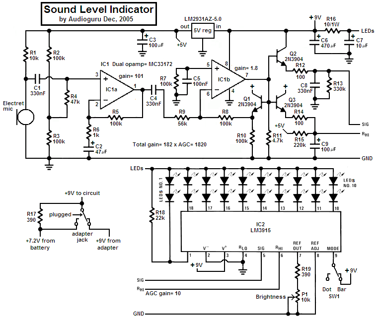
This project utilizes an LM3915 bar-graph integrated circuit (IC) that drives two sets of ten light-emitting diodes (LEDs) across a 30 dB range. The circuit is distinctive as it incorporates an additional 20 dB range through an automatic gain...
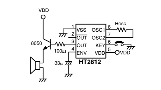
A sound generator is needed for a room monitoring system. Suggestions for an electronic design are requested, as the HT2810 or similar components are not preferred. The sound generator circuit for a room monitoring system can be designed using a...
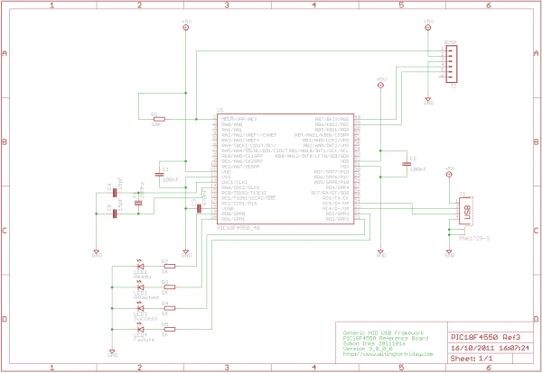
If you have experience with PIC18F microcontrollers and the USB Generic HID standard, you may have noticed the complexity involved in supporting USB on both the PIC18F and the Windows host side. Progressing beyond basic functionalities, such as reading...
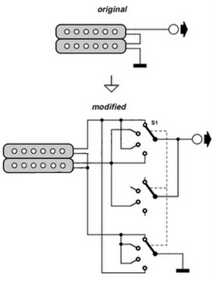
Electric guitars utilize coils, commonly referred to as pickups or elements by guitarists, to transform string vibrations into electrical signals. Typically, a guitar is equipped with multiple elements, allowing the musician to select which element or combination of elements...
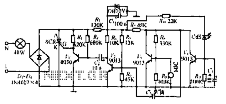
120V galvanic acupuncture salmon RI. The system features a wind-down rectification and a limit irrigation mechanism to achieve an amplitude of 24V. It includes isolation diodes and a steady stream over the circuit. The design ensures that a voltage...
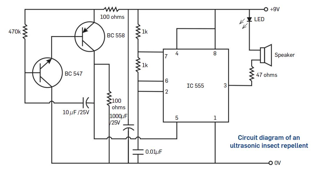
Many types of insects are sensitive to ultrasonic sounds, which can cause them irritation. This project is designed to repel insects such as mosquitoes and cockroaches using ultrasonic sound waves. The project utilizes an ultrasonic frequency generator, which emits sound...