
Sound Generator

The sound generator circuit for a room monitoring system can be designed using a combination of basic electronic components such as operational amplifiers, resistors, capacitors, and a microcontroller or a dedicated sound synthesis IC. This design will provide flexibility and customization for various sound outputs.
One possible approach is to utilize a 555 timer IC configured in astable mode to generate a square wave signal. The frequency of the output can be adjusted by selecting appropriate resistor and capacitor values. This square wave can then be fed into a low-pass filter circuit, which consists of a resistor and capacitor in series, to produce a sine wave output. The filtered signal can be amplified using an operational amplifier to drive a small speaker or piezo buzzer.
For more advanced sound generation, a microcontroller such as an Arduino can be employed. The microcontroller can be programmed to produce different sound patterns or tones based on specific triggers from the room monitoring system. This could include alarm sounds, notifications, or ambient noise. The microcontroller can interface with a digital-to-analog converter (DAC) to produce high-quality audio signals, which can then be amplified and output through a speaker.
In terms of power supply, the circuit can be powered by a standard DC power source, ensuring that all components operate within their specified voltage ranges. To enhance the design, a power management system can be incorporated to ensure efficient energy use, especially if the monitoring system is intended to be battery-operated.
Additionally, the circuit should include protection mechanisms such as diodes to prevent reverse polarity and fuses to protect against overcurrent conditions. Proper PCB layout and component placement are essential for minimizing noise and ensuring stable operation of the sound generator within the room monitoring system.
This comprehensive design can be tailored to meet specific requirements and preferences while avoiding the use of the HT2810 or similar components.Hello all, I would like to built a sound generator for my Room Monitoring system.Can someone suggest me any electronic design as I would not like to use HT2810 or H.. 🔗 External reference
Related Circuits
This sound level meter serves as an effective one-chip replacement for standard analog meters. It is entirely solid-state, ensuring durability and longevity. The circuit is built around the LM3915 audio level integrated circuit (IC) and requires only a minimal...
The function generator features two BNC outputs: one for the high speed [1 to 8 MHz] square signal (BNC1) and another for the DDS signal (BNC2). Offset and amplitude can be regulated by two potentiometers: offset in range of...
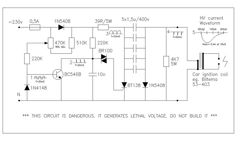
This circuit generates high voltage pulses from a 230 VAC line voltage. The drive end's swing comparator circuit was developed by the creator of this page. The working end is derived from a stroboscope trigger supply circuit. All circuits...
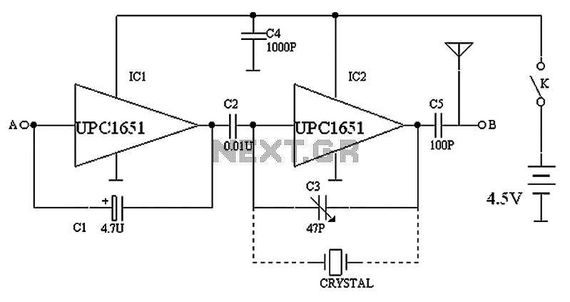
The circuit depicted in the figure includes IC1 and C1, which form a low-frequency oscillator operating at approximately 400 Hz. IC2 and C3 are configured to create a frequency oscillator around 37 MHz. The low-frequency signal is output from...
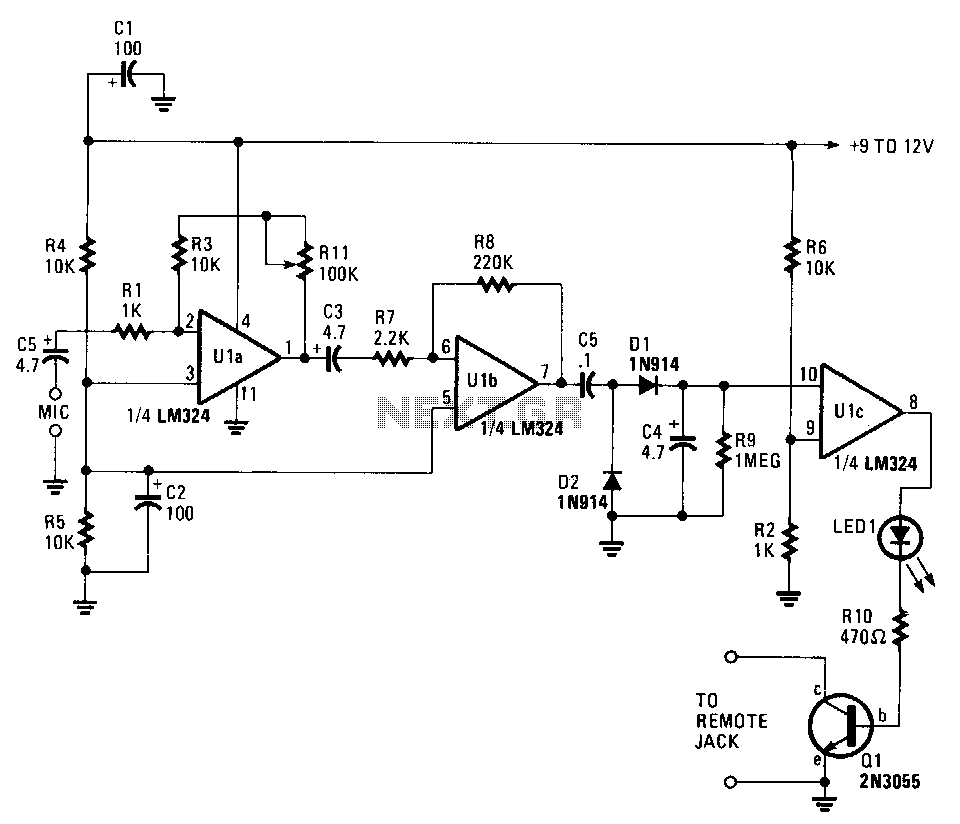
This circuit can cause a cassette recorder to automatically turn on and record when a sound or noise is present. Another use is when the sound-activated switch is used to turn on a cassette player, allowing it to function...
Stepper motors are a recurring subject. This circuit converts a clock signal from a square wave generator into signals with a 90-degree phase shift. Stepper motors are widely used in applications requiring precise control of angular position, speed, and acceleration....