
usb switch schematic circuit

The electronic isolator circuit leverages the 74HC4066 quad analog switch to create a reliable solution for managing USB device connections. The circuit design includes two analog switches dedicated to isolating the data lines, which prevents any unintended communication during power cycling or reset operations. The bistable flip-flop configuration, achieved using the remaining two switches, provides a stable on/off state for the USB connection, preventing accidental disconnections.
The power MOSFET is a critical component in this design, as it controls the power supplied to the USB device. This ensures that the device is powered only when the user intends to connect it to the PC, thereby prolonging the lifespan of both the USB connector and the peripheral hardware. The inclusion of capacitor C2 is essential for initializing the flip-flop state, ensuring that the device remains in a safe "not connected" state upon power-up.
The circuit's design prioritizes user convenience and hardware longevity. By implementing a simple pushbutton mechanism, users can easily manage the connection status of their USB devices, eliminating the need for physical disconnections. The layout can be compactly arranged on a perf-board, making it accessible for hobbyists and engineers alike. Overall, this electronic isolator circuit represents an effective solution for anyone working with USB peripherals, enhancing both usability and durability.Anyone experimenting or developing USB ported peripheral hardware soon be comes irritated by the need to disconnect and connect the plug in order to reestablish communication with the PC. This process is necessary for example each time the peripheral equipment is reset or a new version of the firmware is installed.
As well as tiresome it eventuall y leads to excessive contact wear in the USB connector. The answer is to build this electronic isolator which disconnects the peripheral device at the touch of a button. This is guaranteed to reduce any physical wear and tear and restore calm once again to the workplace.
The circuit uses a quad analogue switch type 74HC4066. Two of the switches in the package are used to isolate the data path. The remaining two are used in a classic bistable flip-flop configuration which is normally built using transistors. A power MOSFET switches the power supply current to the USB device. Capacitor C2 ensures that the flip flop always powers-up in a defined state when plugged into the USB socket (B` in the diagram).
The peripheral device connected to USB socket A` will therefore always be not connected` until pushbutton S2 is pressed. This flips the bistable, turning on both analogue gates in the data lines and switching the MOSFET on.
The PC now recognises the USB device. Pressing S1 disconnects the device. The circuit does not sequence the connections as a physical USB connector does; the power supply connection strips are slightly longer than the two inner data carrying strips to ensure the peripheral receives power before the data signals are connected. The electronic switch does not suffer from the same contact problems as the physical connector so these measures are not required in the circuit.
The simple circuit can quite easily be constructed on a small square of perforated strip-board. The design uses the 74HC(T)4066 type analogue switch, these have better characteristics compared to the standard 4066 device. The USB switch is suitable for both low-speed (1. 5 MBit/ s) and full-speed (12 MBit/s) USB ports applications but the proper ties of the analogue switches and perf-board construction will not support hi-speed (480 MBit/s) USB operation.
🔗 External reference
Related Circuits
In night photography, long exposures are common, sometimes lasting several seconds to several minutes. HDR techniques often require taking a series of nine or more photos. Holding a remote trigger for an extended period can be tedious, leading to...
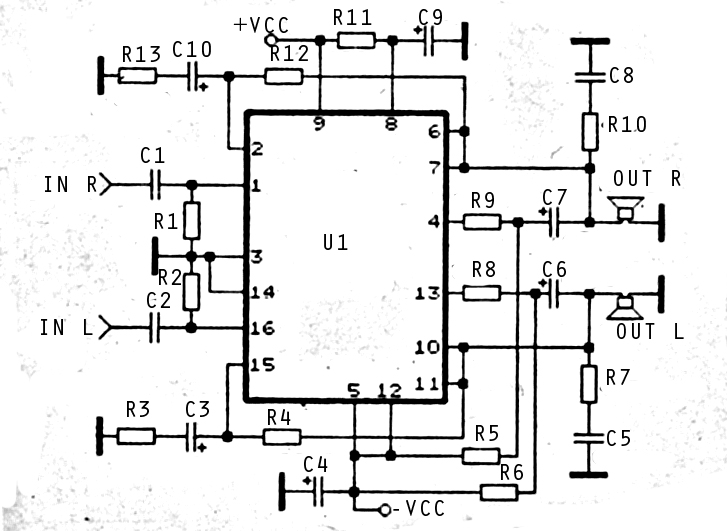
The audio amplifier circuit is highly suitable for home use, particularly with subwoofer or woofer speakers. Commonly referred to as a home amplifier, these audio amplifiers are based on integrated circuits (ICs), specifically the STK series, which includes models...

The schematic diagram below illustrates a high voltage generator circuit. This circuit employs a 4049 hex inverter configured as an oscillator, and it can utilize an ignition transformer from an automotive engine. A fly-back transformer may also be suitable....
This Wien bridge oscillator is straightforward and, like all Wien oscillators, exhibits low distortion. The resonance frequency can be easily adjusted. The Wien bridge oscillator is a type of electronic oscillator that generates sine waves. It is based on the principle...
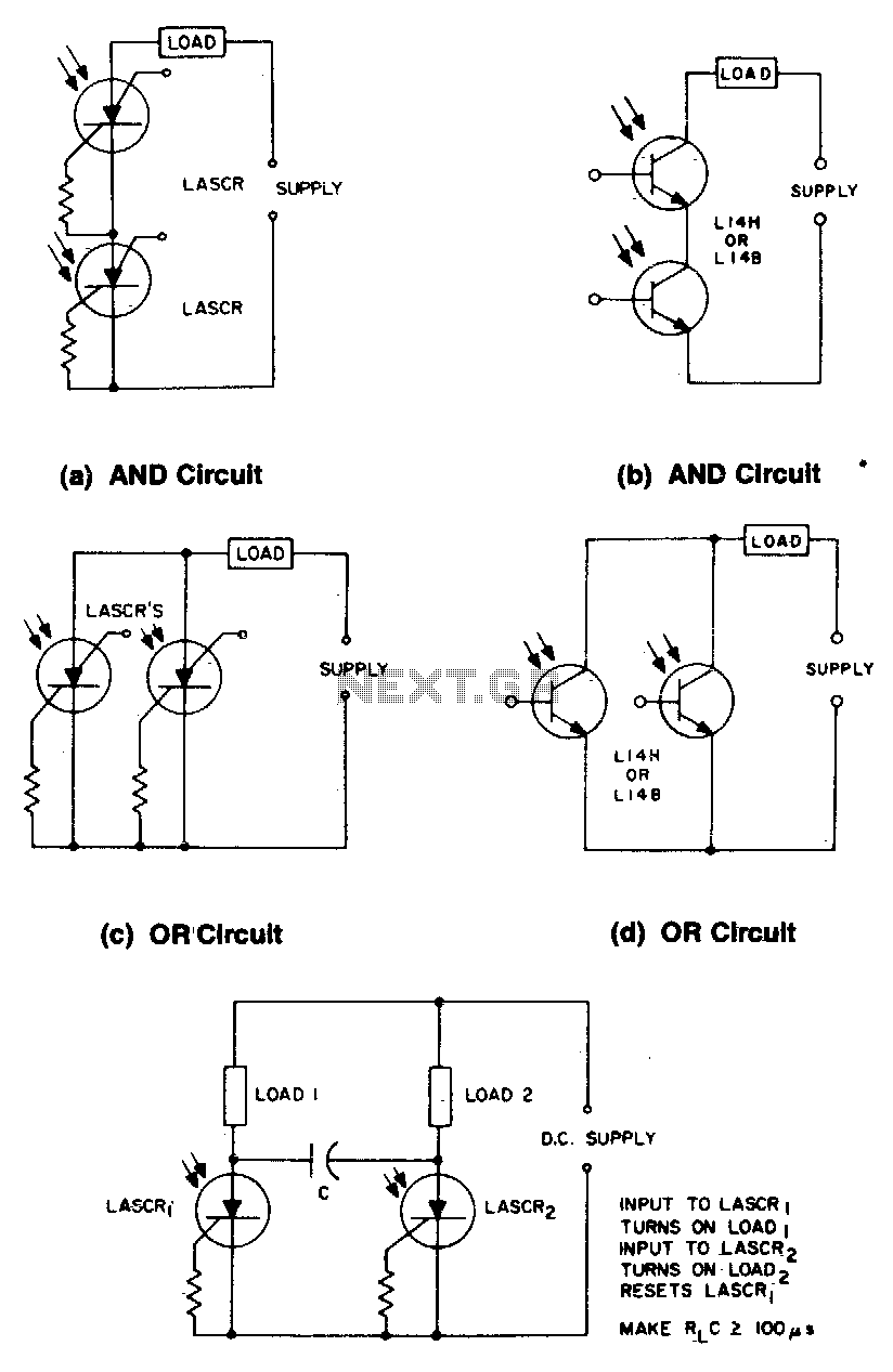
These circuits illustrate some of the common logic functions that can be implemented. The provided circuits serve as examples of fundamental logic functions utilized in digital electronics. Logic functions are the building blocks of digital systems, enabling the execution of...
Based on the classic Baxendall tone control circuit, this provides a maximum cut and boost of around 10dB at 10K and 50Hz. As the controls are passive, the last transistor provides a slight boost. The output is designed to...