
Use a transistor and an ammeter to measure inductance

Bipolar junction transistors (BJTs) are semiconductor devices that play a crucial role in electronic circuits by enabling the control of current flow. In a BJT, there are three regions: the emitter, base, and collector. The emitter is designed to inject charge carriers (electrons or holes) into the base region, which is typically thin and lightly doped. The base region controls the flow of carriers from the emitter to the collector, which is usually more heavily doped and has a larger area.
When a small input current is applied to the base terminal, it allows a much larger current to flow from the emitter to the collector. This current amplification property is fundamental in various applications, including signal amplification, switching, and oscillation circuits. The ability to control a high current with a low input current makes BJTs essential components in analog and digital electronics.
In terms of measuring inductance, the BJT can be employed in a circuit configuration known as a current amplifier or a transimpedance amplifier. By connecting an inductor in series with the emitter or collector, the change in current due to the inductance can be measured. The inductance can be inferred from the relationship between the input current and the output voltage, allowing for accurate measurements of the inductive component.
Furthermore, BJTs can be integrated into various measurement circuits, including LCR meters, where they facilitate the measurement of inductance (L), capacitance (C), and resistance (R). The output characteristics of the transistor can be analyzed to derive the inductance value, making BJTs versatile tools in electronic measurement applications.Bipolar junction transistors transfer a current from a lower-resistance emitter to a higher-resistance collector. You can use this property to measure inductance.. 🔗 External reference
Related Circuits
This simple circuit is designed to test transistors in a circuit, capable of measuring down to 40 ohms across the collector-base or base-emitter junctions. It is also suitable for checking output power transistors in amplifier circuits. The operation of...
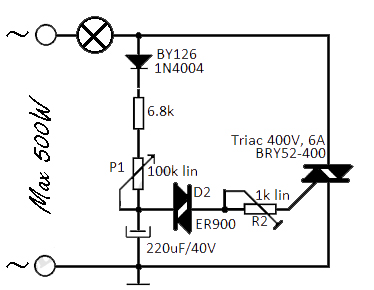
This flashing light circuit utilizes triacs to produce an intermittent light with a variable frequency. Additional components include a diode (D1) and a semi-adjustable potentiometer (R2). The trigger capacitor (C1) is increased from 0.1 µF to 220 µF to...
This is a classic 2-transistor astable multivibrator. Many other NPN small signal or switching transistors can be used, including 2N4401, PN2222, or 2N2222 using the circuit on the left. The circuit can also be inverted using PNP transistors such...
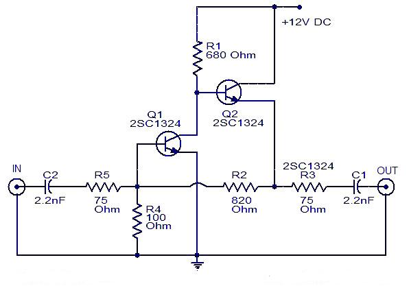
This is a cable TV amplifier utilizing two transistors. The amplifier circuit is designed for cable TV systems using 75 Ohm coaxial cables and operates effectively up to 150 MHz. Transistor T1 is responsible for amplification, providing an expected...
This circuit is designed to protect a power supply or battery. The electric current will be interrupted by a relay when a short circuit occurs. Relays must be selected with a voltage rating equal to the input voltage. It...
The output of this circuit is push-pull and consumes less than 3 mA (with no signal) but drives the earpiece to a very loud level when audio is detected. This circuit operates in a push-pull configuration, which allows it to...