
2 Transistor LED Flasher

The described circuit functions as a classic astable multivibrator, which is a type of oscillator that continuously switches between its high and low states without requiring any external triggering. This circuit employs two NPN transistors arranged in a feedback configuration to produce a square wave output. The choice of transistors is flexible; common options include the 2N4401, PN2222, or 2N2222, all of which are suitable for this application due to their switching capabilities.
In the inverted configuration, PNP transistors such as the 2N3906, 2N4403, PN2907, or 2N2907 can be utilized, allowing for versatility in design based on component availability or specific circuit requirements. The resistors, particularly the 470-ohm ones, play a critical role in controlling the brightness of the connected LEDs. A lower resistance value results in a higher current flow, thus increasing the brightness of the LEDs. For LEDs that require more current or operate at higher voltages, such as green and yellow LEDs, using a 300-ohm resistor may yield better performance.
The timing characteristics of the multivibrator are determined by the RC time constant, which is a product of the resistance and capacitance values in the circuit. In this case, a 39K-ohm resistor in conjunction with a 10uF capacitor establishes the duration of the high and low states of the output waveform. It is important to note that the RC time constants for the two sides of the circuit do not need to be identical; adjusting the resistance or capacitance on one side can effectively alter the duty cycle, allowing for customization of the output frequency and pulse width. With the specified component values, the circuit achieves a flash rate of approximately 1 cycle per second, maintaining a duty cycle of around 50%. This configuration makes it suitable for applications such as LED flashers or simple timers in various electronic projects.This is a classic 2 transistor astable multivibrator. Many other NPN small signal or switching transistors can be used, including 2N4401, PN2222 or 2N2222 using the circuit on the left. The circuit can also be inverted using PNP transistors such as 2N3906, 2N4403, PN2907, or 2N2907 as shown to the right.
The 470 ohm resistors determine the LED bri ghtness. Lower resistance means higher current, and more light. LEDs that require more current or have a higher operating voltage (such as green and yellow) may work better with 300 ohms. The RC time constant of the 39K ohms resistor and the 10uF capacitor determines the on time for each side.
(The two sides do not need to match - vary the RC time constant for one side to get a lower or a higher duty cycle). With the values shown, the flash rate is about 1 cycle per second at 50% duty cycle. 🔗 External reference
Related Circuits
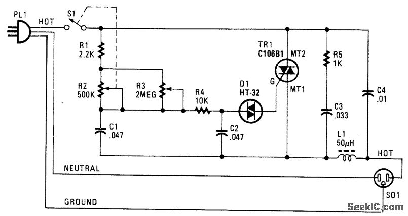
The following circuit illustrates a Phase Controlled Triac (HT-32) Circuit Diagram. Features include a simple circuit design, and bilateral triggering diacs provide a... The Phase Controlled Triac circuit, utilizing the HT-32 component, is designed for applications requiring precise control of...
This circuit is a digital panel meter (DPM) featuring an analog bar graph display and a 3.5-digit digital display. The ICL7107 is configured for 200mV input. The U4A operational amplifier (LF353) amplifies the 200mV full-scale input to the required...
A peak level indicator when a signal exceeds a certain maximum value. It can be quite useful, for instance, with tape recorders, mixing consoles etc. One of the most important requirements of a peak level indicator is that it...
Here is a schematic of a rechargeable 9-LED flashlight using two Gates SLA cells and nine LEDs. It is as bright as when the single bulb was used, and lasts 3 times longer per charge. That is about 10...
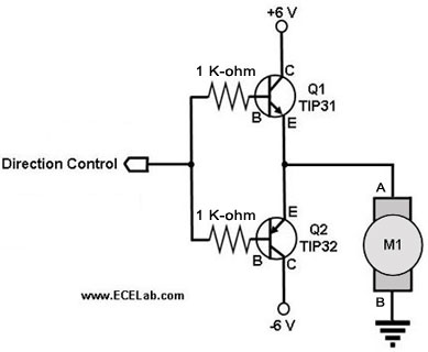
The following circuit illustrates a two-transistor DC motor driver circuit diagram. This circuit utilizes the TIP32 transistor. Features: operates in... The two-transistor DC motor driver circuit is designed to control the operation of a DC motor using two NPN transistors,...
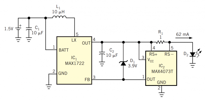
Although white LEDs are common in a variety of lighting applications, their 3 to 4V forward-voltage drop makes low-voltage applications challenging. Charge pumps and other ICs are available for driving white LEDs, but they generally don't work with the...