
Use for the Tesla Switch

The provided text appears to be a conversation regarding the evaluation of progress on a project, specifically referencing a design called ScratchRobot. To create a comprehensive electronic schematic description, it is essential to clarify the context and technical details of the ScratchRobot design.
The ScratchRobot is an educational robotics platform designed to facilitate learning in programming and electronics. It typically integrates a microcontroller, such as an Arduino or Raspberry Pi, with various sensors and actuators to create an interactive and programmable robot. The schematic for such a design would include the following key components:
1. **Microcontroller Unit (MCU)**: The heart of the ScratchRobot, responsible for processing inputs from sensors and controlling outputs to actuators. The schematic should depict the connections between the MCU and other components, highlighting the power supply pins, ground connections, and I/O pins used for communication.
2. **Power Supply Circuit**: This section of the schematic should illustrate how the robot is powered, whether through batteries, a USB connection, or an external power supply. It is crucial to include voltage regulators if different components require different operating voltages.
3. **Input Sensors**: Various sensors may be included in the design, such as ultrasonic distance sensors, infrared sensors, or light sensors. The schematic should show how these sensors connect to the MCU, including any necessary pull-up or pull-down resistors.
4. **Output Actuators**: The ScratchRobot may utilize motors, servos, or LEDs as output devices. The schematic must detail the connections for motor drivers or relay circuits that control these actuators, ensuring that the power requirements and control signals are appropriately managed.
5. **Communication Interfaces**: If the ScratchRobot is designed to communicate with other devices or networks, the schematic should include details on communication protocols such as I2C, SPI, or UART. This may involve additional components like transceivers or Bluetooth modules.
6. **User Interface**: Depending on the complexity of the ScratchRobot, a user interface might be included, such as buttons or a touchscreen. The schematic should provide details on how these components are wired to the MCU.
7. **Debugging and Programming Ports**: It is advisable to incorporate programming headers or debugging ports in the schematic to facilitate easy access for code uploading and troubleshooting.
Overall, a well-structured schematic for the ScratchRobot will provide a clear visual representation of all components, their interconnections, and the operational flow of the system. Proper labeling and annotations will enhance understanding and facilitate further development or modifications to the design.Thank you very much I will try that. @StevanC What do you think, are we making some progress or should we stick to your design scratchrobot.. 🔗 External reference
Related Circuits
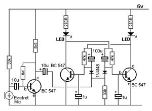
The Voice Electric (FC52) converts sound into electrical signals. The FC52 utilizes a high-gain glucose amplifier to amplify audio signals. When a clapping sound occurs, the sound signal is transformed into electrical signals and fed into the inverting input...
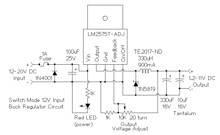
This is a simple buck mode switching regulator circuit diagram. This circuit is more efficient; switch mode regulators convert DC input voltage to pulses of high DC voltage. The DC pulses are used to charge a storage capacitor to...
4QD manufactures motor speed controllers, and all their H bridges utilize PWM. This is a simple switch circuit designed for reversing and stopping a motor without speed control. Two inputs, A and B, control the bridge. When both inputs...
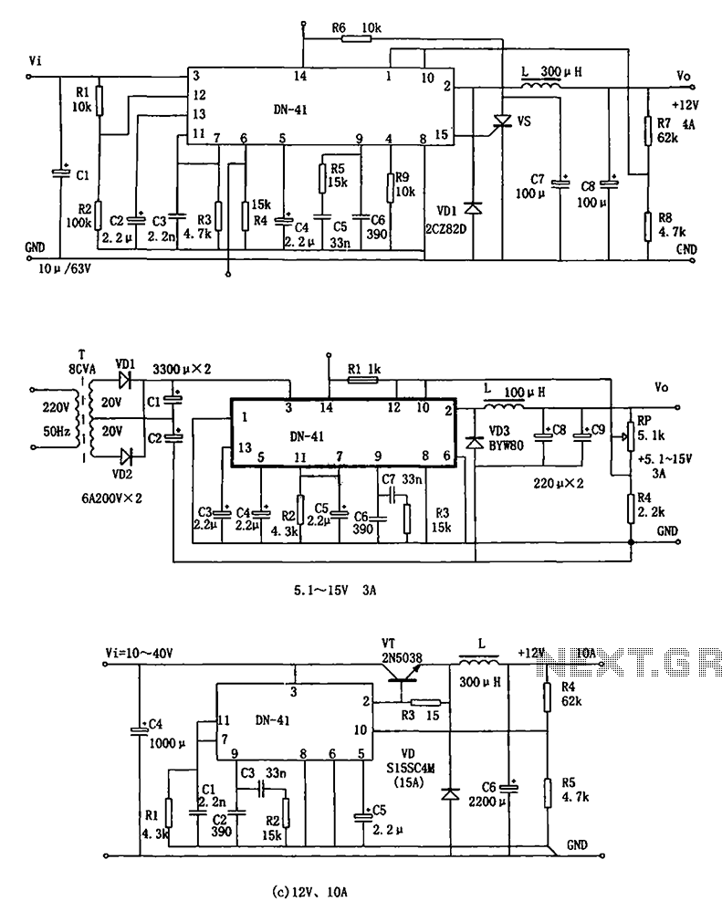
The DN-41 is a high-current switching regulator that includes an overcurrent and overvoltage (crowbar) protection circuit, a reset circuit, and a soft start feature. It is designed to operate with fewer external components while maintaining stability, safety, and reliability....
A 1999 S10 2.2L Fuse Box inquiry involves identifying the main power terminals located at the top left and right of the Fuse Box. The question pertains to which terminal serves as the full-time power terminal and which one...
This electronic timer switch will turn on a light for 100 seconds, turn it off for another 100 seconds, and then turn it on again for 100 seconds after an hour of powering up the circuit. It is a...