
H bridge switch for small motors

The motor control circuit described utilizes a half-bridge configuration to achieve basic motor control functions, specifically forward, reverse, and off states. The inputs A and B provide a straightforward interface for controlling the motor's operation. When both inputs are high, the circuit effectively disables the motor by connecting both terminals to ground (0V), ensuring no current flows through the motor windings.
The activation of Tr2 by setting input A low allows the current to flow in a direction that drives the motor forward. In contrast, activating Tr6 by setting input B low reverses the current flow, thus reversing the motor's direction. This simple control mechanism is effective for applications where precise speed control is not required.
The half-bridge configuration operates using complementary Darlingtons, which enhances the current handling capabilities and provides a robust switching solution. The inclusion of Tr1 as the input to the top Darlington transistor replaces the conventional pull-up resistor, streamlining the design and potentially improving response times.
The absence of provisions for recirculating motor currents when the switch is turned off is a notable design choice. While this may not pose issues for small motors due to their lower energy release, it is advisable to consider adding flywheel diodes to manage inductive kickback effectively. These diodes can protect the transistors from voltage spikes that occur when the motor is de-energized, thereby prolonging the lifespan of the components.
The selection of transistors is critical for the circuit's performance. The use of 2N3053 and BC214 transistors in the original design illustrates the importance of choosing components that can handle the required current and voltage levels. It is essential to ensure that the transistors selected can switch the motor safely and efficiently to prevent overheating or failure during operation.
Overall, this motor control circuit provides a fundamental yet effective solution for applications requiring simple motor direction control without the complexity of speed regulation.4QD manufacture motor speed controllers so all our H bridges are PWM. Here`s a simple switch circuit for reversing and stopping a motor without any control of speed. Two inputs, A and B, control the bridge. With both high (or open circuit) both ends of the motor are connected to 0v. Connect A low and Tr2 turns on causing the motor to go forward. C onnect B low and Tr6 turns on, reversing the motor. If A and B are both low, both ends of the motor are high, so the motor is off. Another way of looking at he half bridge is as a totem-pole output stage, with both transistors as complementary darlingtons. The resistor which would normally pull up the base of the top of th pole is replaced by Tr1 which forms also the input to the top-of-the-pole darlington.
Note that no provision is made for recirculating motor currents at switch off. Since the motor is relatively small, the energy at switch off is small and as the circuit is not switching at a high rate, the dumped energy is small, so the breakdown energy in the transistors is not a problem. However - you may like to put reverse parallel flywheel diodes across the transistors. In the original TO5 transistors were used: 2N3053 for the even numbers and BC214 for the odd numbers.
The circuit`s nice in that respect - it uses NPN power transistors and PNP drivers in each section of the bridge. You have to chose transistors that will safely switch your motor. We aim to transmit more information by carrying articles. Please send us an E-mail to wanghuali@hqew. net within 15 days if we are involved in the problems of article content, copyright or other problems.
We will delete it soon. 🔗 External reference
Related Circuits
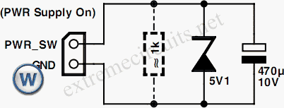
An additional push-button switch is typically required for the ATX Power Switch/Soft Power Switch signal; however, this simple circuit eliminates that need. The design is effective and has undergone extensive testing. A zener diode is included to protect against...

The TDA7560 is a quad bridge car audio amplifier that delivers 4 x 50 watts of power. It features inputs compatible with TDA7560 soil and can handle very high input signals (± 8Vpk) without compromising performance. When standard input...
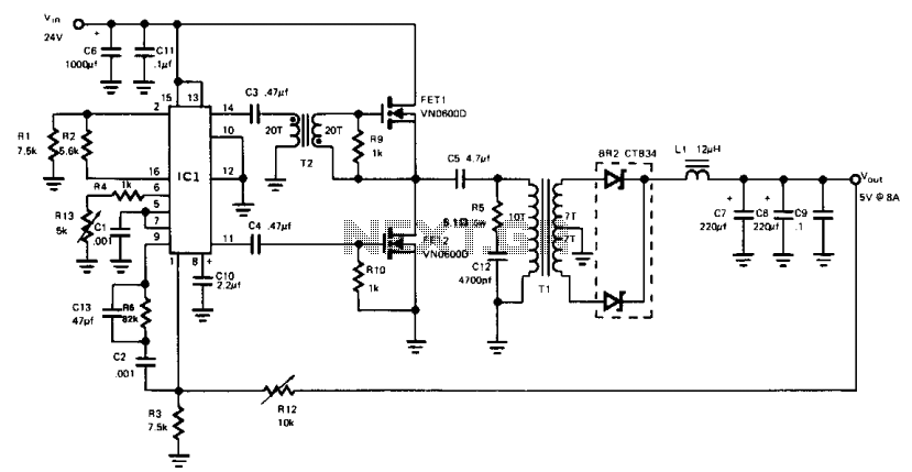
This buck-derived circuit delivers up to 8 A at 5 V DC while operating within an input voltage range of 24 to 32 V DC. The circuit utilizes two power MOSFETs that conduct alternately for equal durations. The switching...
Many electric vehicles can convert the momentum of the car into stored energy in batteries, instead of dissipating it as heat in the brake pads. This process is known as regenerative braking. It can be implemented using a motor...
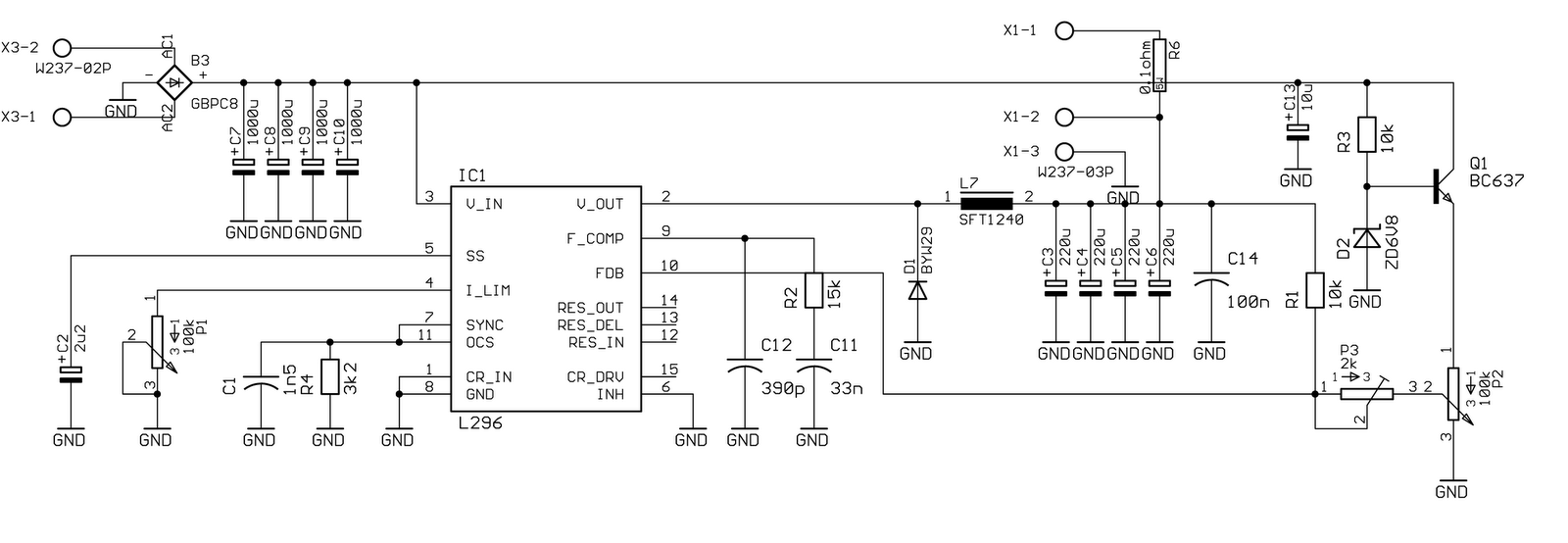
Specifically for the chip used in this circuit, the data is as follows: The oscillator operates at a frequency of 200 kHz, with output noise below 1% (worst case). The maximum current is 4 A at 20 V. The...
A basic Wien Bridge Oscillator utilizes a filament lamp in conjunction with an operational amplifier (op-amp). The property of filament lamps, specifically the non-linear increase in resistance of the tungsten filament as it heats, plays a crucial role in...