
Using an external transistor ten-band equalizer

The ten-band equalizer circuit described employs the TA7796 integrated circuit, which is designed for audio signal processing and is capable of providing adjustable gain across multiple frequency bands. The use of five external transistors enhances the circuit's ability to amplify and filter audio signals, allowing for precise control over the tonal qualities of the sound output.
In this configuration, the lowest center frequency of 100 Hz targets the bass frequencies, ensuring that low-end sounds are effectively managed. The highest center frequency of 16 kHz addresses the treble range, allowing for clarity and brightness in audio playback. The selection of a crystal tube in conjunction with the 9014 transistor is notable for its role in maintaining signal integrity and minimizing distortion within the equalizer circuit.
The p-value of 500 indicates the gain factor that is applied within the circuit, influencing the overall output level and responsiveness of the equalizer. This value is crucial for achieving the desired balance between the various frequency bands and ensuring that the audio output is tailored to the specific requirements of the listening environment.
Overall, this ten-band equalizer circuit exemplifies a sophisticated approach to audio signal processing, combining the capabilities of the TA7796 with external components to deliver a versatile and high-performance audio equalization solution.Another example of application is extended. It uses TA7796 and five external transistor to form a ten -band equalizer circuit, the lowest center frequency of the equalizer for the 1001-L :, highest center frequency circuit 16kffio crystal tube using 9014 and other, p value should be 500.
Related Circuits
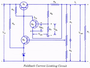
If the load resistance (RL) is reduced or the load terminals are accidentally shorted, a very large load current will flow, potentially damaging the pass transistor (Q1), diode, or other components. Fuse protection may not be sufficient, as the...
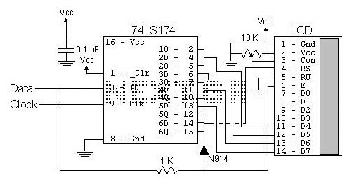
The most popular LCD interface is the Hitachi 44780 based LCD controller chip which provides a fairly easy to work with interface and low power consumption. The major drawback of the interface is the perceived complexity of working with...
The basic circuit using the L293 forms an H-Bridge driver, as shown in Figure 1, is designed for controlling inductive loads like DC motors. External diodes are necessary for suppressing back EMF. The MiniBoard utilizes the L293D, which features...
The electronic diagram of the monophonic FM receiver made with TDA7088T is shown on Pic.4.12. If built with SMD components it can be placed in a matchbox, altogether with two button-type batteries. The operating principle of this device is...
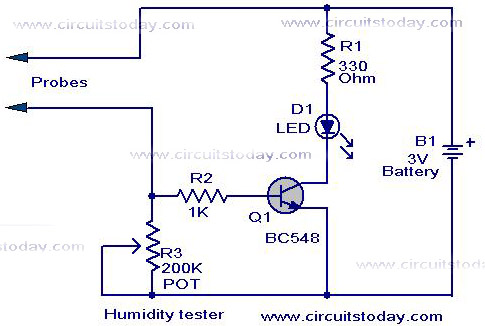
A simple humidity tester circuit using only an LED, a transistor, and a few resistors is explained with a clear circuit schematic. The humidity tester circuit is designed to provide a visual indication of humidity levels using basic electronic components....

This transistor ignition circuit enhances vehicle starting and ensures smoother engine operation, especially at both high and low RPMs. It contributes to lower fuel consumption, reduced emissions, and decreased maintenance costs. The system promotes economical and electronic driving. The transistor...