
Transistor Ignition

The transistor ignition circuit is designed to optimize the ignition timing and improve the overall performance of an internal combustion engine. It employs a transistor-based switching mechanism that replaces traditional mechanical points, leading to more precise control over the ignition process. This increased precision allows for better combustion efficiency, which results in enhanced power output and smoother engine operation across a wider range of RPMs.
Key components of the circuit typically include a power transistor, a resistor, a capacitor, and a series of diodes. The power transistor acts as a switch that controls the flow of current to the ignition coil. When the ignition key is turned, the circuit is energized, allowing the capacitor to charge through the resistor. Once the voltage across the capacitor reaches a certain threshold, the power transistor switches on, delivering a high-voltage pulse to the ignition coil. This pulse generates a spark at the spark plugs, igniting the air-fuel mixture in the combustion chamber.
The use of a transistor instead of mechanical points eliminates issues such as point bounce and wear, resulting in increased reliability and reduced maintenance. Additionally, the circuit can be designed to include features such as adjustable timing and dwell control, allowing for further optimization based on specific engine characteristics.
Overall, this transistor ignition circuit not only improves the operational efficiency of the vehicle but also supports environmental sustainability by reducing harmful emissions. As a result, it is a valuable upgrade for enhancing vehicle performance and longevity while promoting economical driving practices.This transistor ignition circuit give your car to have better starting and smoother running, particularly at very high and very low RPM. Lower fuel consumption, less pollution, lower servicing costs. Drive economically, drive electronically.. 🔗 External reference
Related Circuits
The motor is utilized to provide the mechanical output of the system and to move the potentiometer for loop closure. For high-power servos, three-phase motors can be employed. Potentiometer: A simple potentiometer can be used for standard industrial applications...
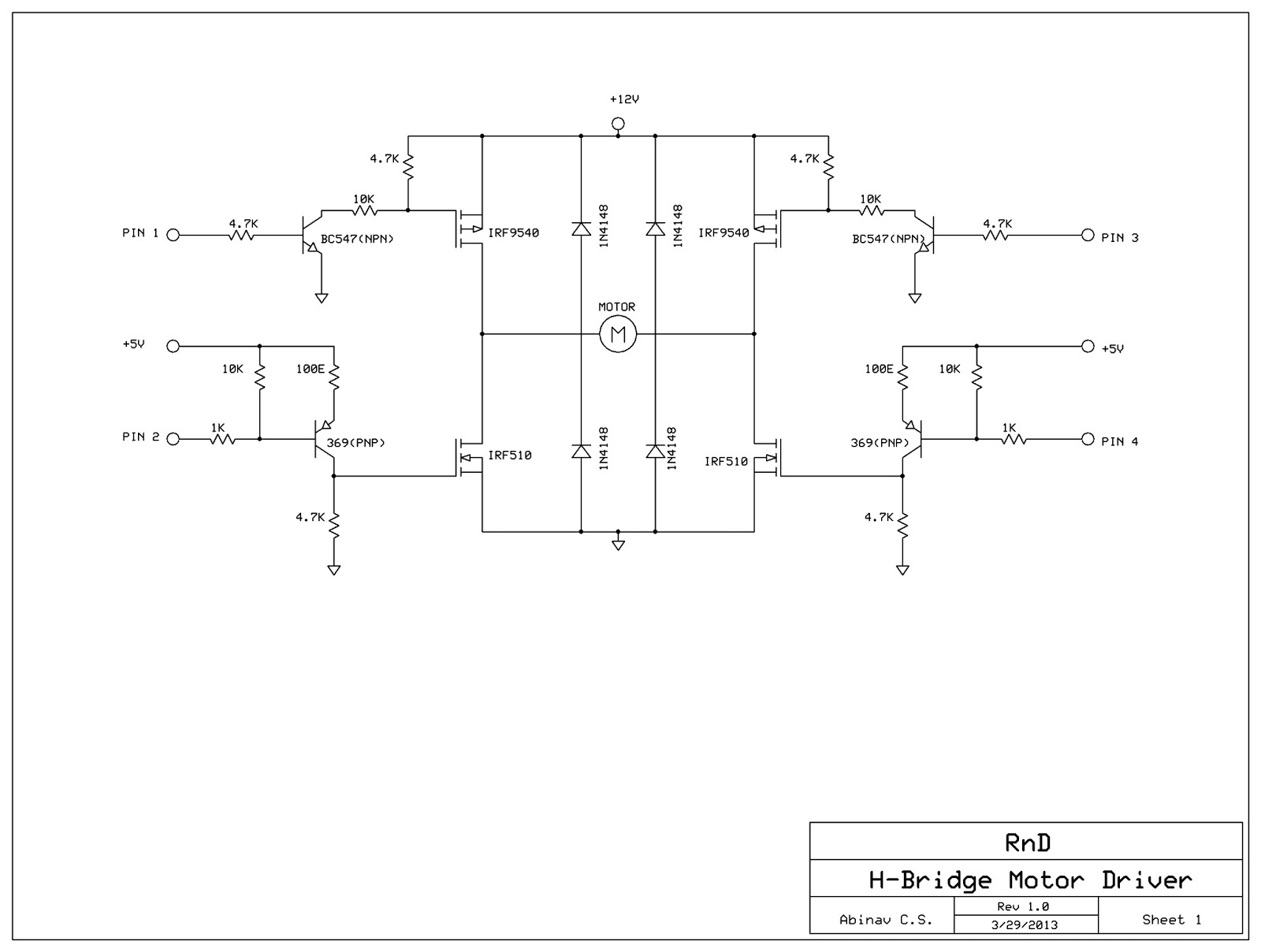
This post discusses the construction of an H-Bridge Motor Driver circuit using simple MOSFETs and transistors. The primary feature of this H-Bridge is its ability to drive a motor in both directions. An H-Bridge is a circuit that allows...
This low-cost bass treble circuit consists of capacitors, resistors, and two potentiometers for bass and treble control. The circuit can be assembled without a veroboard, as the components can be soldered directly due to the simplicity of the design....

6502 fully simulated at the transistor level. The simulator can be run in your browser. They are also taking submissions for other ICs to model. The 6502 microprocessor, originally designed by MOS Technology, is a popular 8-bit CPU known for...
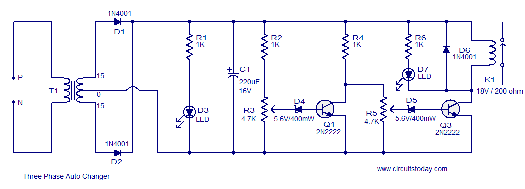
The following circuit illustrates a Three Phase Auto Changer Circuit Diagram. This circuit utilizes the 2N2222 transistor. Features include a transformer. The Three Phase Auto Changer Circuit is designed to automatically switch between different phases in a three-phase power system,...
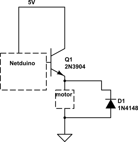
When the motor is connected in this manner, the Netduino activates the transistor, but nothing occurs. Swapping the motor with an LED results in the LED lighting up, indicating that the motor is not receiving sufficient power. Connecting the...