
Using ASCII keyboard code development system

The CY512 system is designed for efficient control of stepping motors, particularly in applications requiring precise movements such as welding or assembly tasks. The immediate command execution mode allows for real-time control, enabling users to input commands that directly influence motor operations. This mode is particularly useful for testing and calibration purposes, providing immediate feedback on the system's response to user inputs.
In programming mode, users can develop custom sequences tailored to specific tasks. The internal memory buffer allows for the storage of user-defined programs, facilitating complex operations without the need for continuous user input. This capability is essential for repetitive tasks, ensuring consistency and reliability in operations. The programming interface is user-friendly, designed to streamline the process of creating and modifying programs.
The execution of stored programs is initiated by simple keystrokes, enhancing operational efficiency. The example provided illustrates a typical application where multiple solder joints must be addressed sequentially. The system's ability to return to a predefined position after completing a task is a critical feature, as it minimizes downtime and prepares the system for the next operation.
Moreover, the CY512 allows for the adjustment of key parameters such as the maximum stepping rate and deceleration ramp rate. These settings are crucial for optimizing the performance of the stepping motor, particularly in applications where precision and speed are paramount. The ability to fine-tune these parameters ensures that the system can adapt to various operational requirements, enhancing its versatility across different tasks.
Overall, the CY512 development system represents a robust solution for applications requiring precise motor control, combining ease of use with advanced programming capabilities.Expressed in ASCII keyboard code CY512 easiest development system. It has three operating modes; 1) the immediate command execution mode. Users type ASCII commands and keyboard parameters ASCII- stepping decimal, you can directly control the stepping motor movement. 2) Enter the programming mode. Type the user program, stored in the memory buffer CY 512 inside. Executive 3) stored program. As long as the key for eight Q/(Exit programming mode) and D/(Start program execution) can be. Heres an example of programming. Consider for a similar workpiece welding procedures, it has six pitch solder joints are 20 steps in each solder joint, the controller connected to external control lines 5s, welding operation. After the completion of the six joints, the motor should be returned to the original position, and other candidates of the next workpiece.
In front of the installation program to set the highest rate stepping, deceleration ramp rate and rate coefficients and other parameters.
Related Circuits
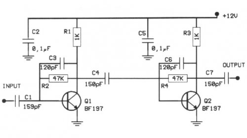
The following circuit illustrates a 20 dB VHF amplifier circuit diagram utilizing the BF197 transistor. Features include a simple circuit design. The 20 dB VHF amplifier circuit is designed to amplify very high frequency signals, making it suitable for applications...
The ISD1000A is a Direct Analog Storage device which allows you to store 20 seconds worth of voice data on an IC chip which can be played back anytime. The data stored will stay in memory even if the...
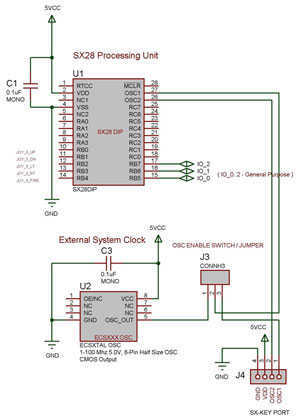
The SX 28 internal oscillator is not that fast, so an external oscillator can be hooked up to the processor as shown in the diagram to increase the operation cycles per second. The SX 28 microcontroller is designed with an...
In this circuit, an NE592 acts as an IF amplifier. DC coupling between mixer and amplifier is practical because different +6 V and +12 V supply voltages are used. The voltage at the differential input is about 4.5 V....
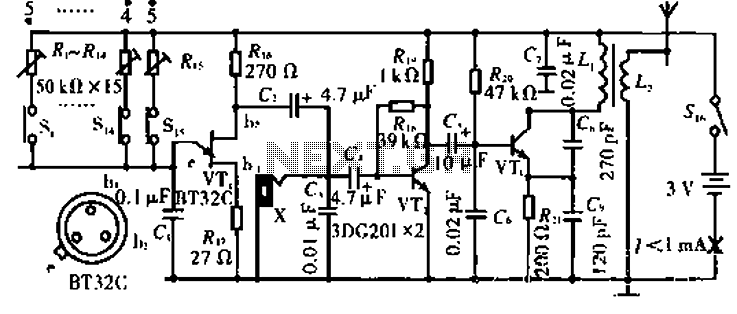
The circuit operates with VT3 and associated components arranged as a common-base capacitance feedback oscillation circuit. The oscillation frequency is set by capacitors C8, C9, and inductor L1. VT2 serves as a voltage amplification stage that reinjects the audio...
This circuit is designed for children's entertainment and can be installed on bicycles, battery-powered cars, motorcycles, as well as models and various games and toys. When switch SW1 is positioned as indicated in the circuit diagram, it generates the...