
Simple Electrification Unit

This circuit is engineered to generate high-voltage pulses suitable for educational purposes and experimentation. The design is inspired by electrified fence generators, which are used for animal containment and security applications. The primary components of the circuit typically include a transformer, a capacitor, a discharge mechanism, and a control circuit.
The transformer steps up the input voltage to a much higher level, which is essential for generating the high-voltage pulses. The capacitor stores electrical energy, allowing it to release a quick burst of high voltage when discharged. The discharge mechanism, often a spark gap or a solid-state switch, is crucial for controlling the timing and duration of the pulse.
To ensure safety during experiments, the circuit should incorporate protective features such as fuses or circuit breakers to prevent overloads. Additionally, it is advisable to include an isolation transformer to separate the high-voltage side from the low-voltage control components, minimizing the risk of accidental shock.
Proper housing and insulation are also required to prevent accidental contact with high-voltage parts. Experimenters should be trained in safety protocols when working with high-voltage circuits to mitigate risks associated with electrical hazards. Overall, this circuit serves as a valuable tool for understanding high-voltage phenomena in a controlled and safe environment.The circuit is intended for carrying out harmless experiments with high-voltage pulses and functions in a similar way as an electrified fence generator. T.. 🔗 External reference
Related Circuits
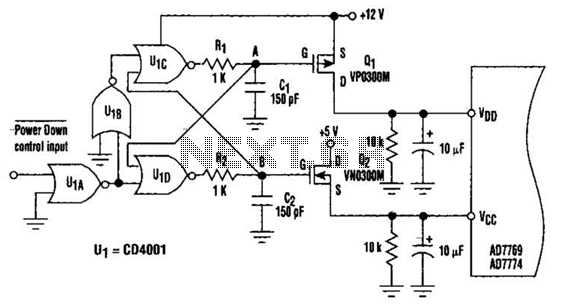
This circuit adds a power-down function to analog I/O ports, such as the AD7769 and AD7774. Additionally, the diodes typically required to protect the devices against power-supply mis-sequencing can be eliminated. In this design, MOSFETs Q1 and Q2 switch...
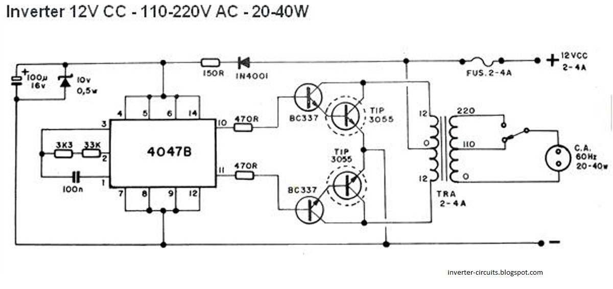
This schematic represents a simple 40W inverter that converts 12V to 220V. It has been functional for four years. The core component of the circuit is a CD4047 integrated circuit (IC) configured as an astable multivibrator. The resistance and...

In this circuit, U1 is a frequency converter that supplies the 455-kHz intermediate frequency (IF) stage U2 and detector U3. U4 serves as the audio output stage. R9 functions as a gain control, allowing for the adjustment of the...
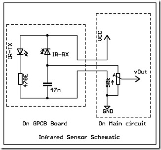
The following circuit illustrates a simple infrared sensor module circuit diagram. Features include a simple infrared sensor module and flame detection. The simple infrared sensor module circuit operates by utilizing an infrared (IR) transmitter and receiver pair. The IR transmitter...
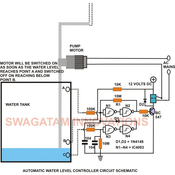
This low-cost water level controller circuit, when built and installed, will efficiently control the water level inside any attached water tank. It helps save electricity and water while relieving users from the hassle of manually switching the water pump...
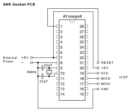
This simple AVR programmer is capable of transferring hex programs to most Atmel AVR microcontrollers. It is more reliable than many other basic AVR programmers available and can be assembled in a short amount of time. This programmer supports...