
voltage conversion circuit composed of NJM4558

The voltage/current conversion circuit depicted in Figure 1-42 (a) employs a precision operational amplifier (op-amp) configured in a non-inverting mode to achieve the desired conversion characteristics. The input voltage, varying from 0 to 10V, is fed into the non-inverting terminal of the op-amp. The circuit incorporates a feedback resistor network, including RP2, which is crucial for calibrating the output current. When RP2 is adjusted to set the input voltage to 0V, the op-amp output drives the current through a transducer or load, resulting in a maximum output current of 20mA. Conversely, when the input voltage reaches its maximum of 10V, the output current is reduced to 4mA, demonstrating the linear relationship between input voltage and output current over the specified range.
In Figure 1-42 (b), the current/voltage conversion circuit is designed to convert the 4-20mA current signal into a corresponding output voltage that spans from -10V to +10V. This circuit typically utilizes a differential amplifier configuration, allowing it to accurately process the current input. The output voltage is achieved through a combination of resistors that set the gain and offset of the amplifier. The resistor adjustments, including those of RP, enable fine-tuning of the output voltage, ensuring that the conversion is linear and adheres to the desired output range. This type of conversion is essential in industrial applications where current loops are standard for transmitting sensor data, and converting these signals into voltage levels is necessary for further processing or display.
Overall, both circuits exemplify critical techniques in signal conversion and conditioning, facilitating interoperability between different electronic systems and enhancing measurement accuracy in various applications.Figure 1-42 (a) is a voltage / current conversion circuit, and it can convert 0-lOV input voltage into 4-2OmA output current. Adjusting RP2 could make Ui = 0, I. = 2OmA; adjusting RP2 could make Ui = lOV, I. = 4mA. Figure 1-42 (b) is the current / voltage conversion circuit, which will convert the 4-2OmA current into -10 to + lOV output voltage.
Adjusting RP.. 🔗 External reference
Related Circuits
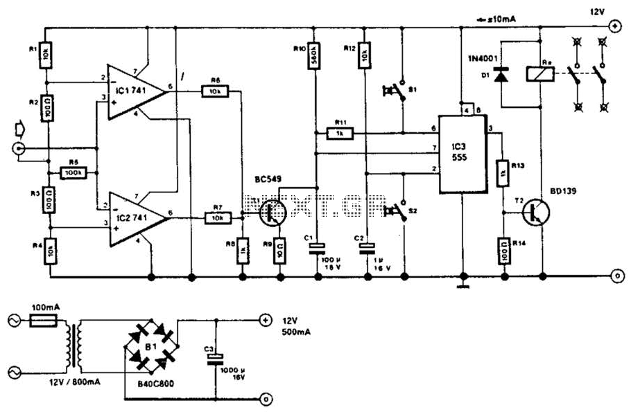
This circuit will disconnect the line supply to audio or video equipment if there has been no input signal for approximately 2 seconds. Switch SI provides manual operation, while switch S2 functions as a reset mechanism. This circuit allows...
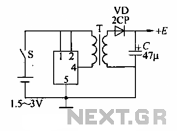
A DC booster circuit is illustrated in the figure, which represents a step-up transformer circuit diagram. The step-up transformer (T) can be utilized to power small transistor radios. The winding ratio can be adjusted to achieve the desired output...
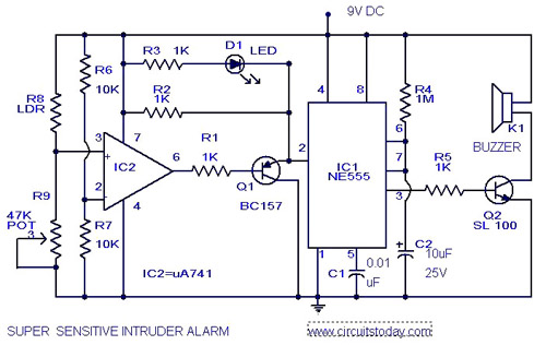
The circuit diagram illustrates an ultra-sensitive intruder alarm. The mere shadow of an intruder passing within a few meters of the circuit is sufficient to activate the alarm. In this setup, the IC2 uA741 is configured as a sensitive...
This circuit serves as a decorative element or indicator, featuring adjustable flashing or dancing speeds of LEDs and the ability to create various light patterns. It consists of two astable multivibrators: one formed by transistors T1 and T2, and...
The 27MHz quartz crystal oscillator circuit is illustrated in figure 1. The biasing circuit consists of resistors R1, R2, and R3, while C6 serves as the bypass capacitor. The partial voltage circuit includes capacitors C1, C2, C3, and C4...
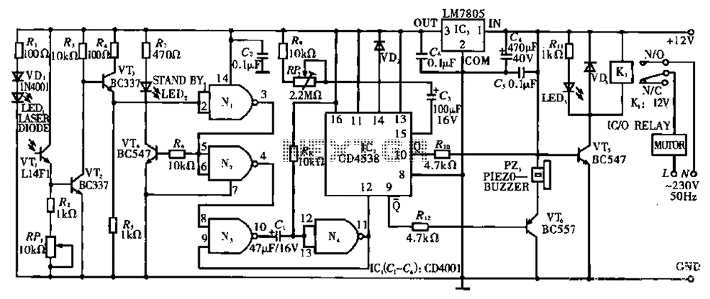
Circuit T operates on the principle of utilizing a laser diode LED as a light emitter. This circuit incorporates a laser diode that serves similar functions as a light-emitting diode. It features a resistor (R) and a diode (VD)...