Sensitive Intruder AlarmCircuit using 555 IC and 741 IC
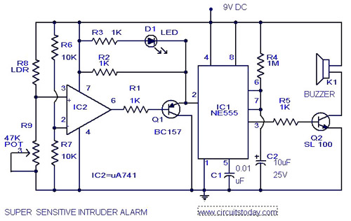
The circuit diagram represents an ultra-sensitive intruder alarm. A shadow from an intruder passing nearby is sufficient to trigger the alarm. The operational amplifier IC2 (uA 741) is configured as a sensitive comparator, with its set point determined by resistors R6 and R7. The voltage divider formed by the Light Dependent Resistor (LDR) and resistor R9 is connected to the non-inverting pin of IC2. In standby mode, these two voltages are equalized by adjusting R9, resulting in a high output (pin 6) from the comparator, which keeps transistor Q1 in the off state. Consequently, the trigger pin of IC1 receives a positive voltage, and the alarm remains inactive. When an intruder approaches the LDR, the shadow causes an increase in its resistance. This change results in different voltages at the inputs of the comparator, leading to a low output from IC2, which turns on Q1. This action generates a negative-going pulse to trigger IC1, configured as a monostable multivibrator. The output from IC1 is then amplified by transistor Q2 (SL 100) to sound the alarm. Proper sensitivity adjustment is crucial; if the desired sensitivity cannot be achieved, a low-resistance potentiometer (approximately 1K ohm) can be added in series with R9 for fine-tuning.
The ultra-sensitive intruder alarm circuit employs a combination of analog components to detect minute changes in ambient light levels caused by the presence of an intruder. The circuit's core component, the uA 741 operational amplifier, functions as a comparator, comparing the voltage levels from the LDR and the reference voltage set by resistors R6 and R7. The LDR's resistance decreases in bright light and increases in darkness, allowing it to detect shadows effectively.
In the circuit's normal operation, the voltage divider formed by the LDR and R9 maintains a balance between the two input voltages of the comparator. Adjustments to R9 allow for calibration of the circuit's sensitivity to ambient light changes. When an intruder casts a shadow on the LDR, the change in resistance alters the voltage at the non-inverting input, causing the comparator's output to switch states.
Transistor Q1 acts as a switch that controls the triggering of the monostable multivibrator (IC1). When the output of the comparator goes low due to the shadow detected by the LDR, Q1 turns on, sending a negative pulse to IC1. This pulse causes IC1 to generate a single output pulse that remains high for a predetermined duration, determined by the external timing components connected to it.
The output pulse from IC1 is then amplified by transistor Q2 (SL 100), which drives the alarm system. This amplification ensures that the alarm can produce a loud sound or signal sufficient to alert individuals in the vicinity of the intrusion.
For optimal performance, it is essential to fine-tune the sensitivity of the circuit. The addition of a low-resistance potentiometer in series with R9 allows for precise adjustments, ensuring that the alarm is triggered only under the desired conditions, thereby minimizing false alarms and enhancing reliability.Here is the circuit diagram of an ultra sensitive intruder alarm. The shadow of an intruder passing few meters nearby the circuit is enough to trigger the alarm. Here IC2 uA 741 is wired as a sensitive comparator, whose set point is set by R6 &R7. The voltage divide by LDR and R9 is given at non inverting pin of IC2. At standby mode these two volt ages are set equal by adjusting R9. Now the output (pin6) of comparator will be high. Transistor Q1 will be off. The voltage at trigger pin of IC1 will be positive and there will be no alarm. When there is an intruder near the LDR the shadow causes its resistance to increase. Now the voltages at the inputs of comparator will be different and the out put of IC2 will be low. This makes Q1 on. This makes a negative going pulse to trigger the IC1 which is wired as a monostable multivibrator. The out put of IC1 will be amplified by Q2 (SL 100) to produce alarm. The sensitivity is very important here. If you cannot adjust the required sensitivity properly, use one LOW resistance (~1K ) POT in series with R9 for fine adjustment. 🔗 External reference
