
using LM334Z with soft start

The LM334Z is a versatile current regulator that can be used in various applications requiring constant current output. It is particularly suited for LED driving, biasing transistors, and other applications where stable current is essential. The device operates by maintaining a constant current flow through a load, independent of variations in supply voltage or load resistance.
In this circuit, a 12V battery serves as the primary power source, and the LM334Z regulates the output current to a fixed value of 2mA. The configuration typically involves connecting the LM334Z in a simple circuit with resistors to set the desired current level. The output current can be adjusted by selecting an appropriate resistor value connected to the set pin of the LM334Z.
To ensure optimal performance, it is crucial to consider the power dissipation across the LM334Z, which can be calculated using the formula P = (Vin - Vout) * Iout. In this case, the input voltage is 12V, the output voltage will depend on the load, and the output current is fixed at 2mA. Adequate heat sinking may be required if the power dissipation exceeds the thermal limits of the device.
The LM334Z also features a wide operating voltage range and can handle load voltages up to 40V, making it suitable for various applications beyond simple battery-powered circuits. Additional components, such as bypass capacitors, may be added to the circuit to enhance stability and transient response.
When designing the circuit, it is important to ensure that the LM334Z is connected correctly, with the input voltage applied to the appropriate pins and the output connected to the load. The ground connections must also be secure to prevent erratic behavior. Proper layout and grounding techniques will help minimize noise and improve the overall reliability of the circuit.A bit of a newbie to creating circuits I have a 12V battery regulated to 2mA with an LM334Z current regulator. Here are the docs for the current regulator: .. 🔗 External reference
Related Circuits
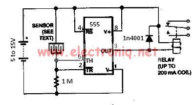
The water sensor circuit utilizes a 555 timer circuit along with common electronic components. It consists of two metal electrodes positioned closely enough that a drop of water can create a conductive bridge between them. If the water is...
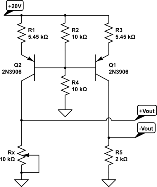
A functional circuit utilizing an operational amplifier (op-amp); however, the instructor indicated that op-amps can be challenging to work with and provided transistors as an alternative. Operational amplifiers (op-amps) are versatile components commonly used in various electronic circuits for...
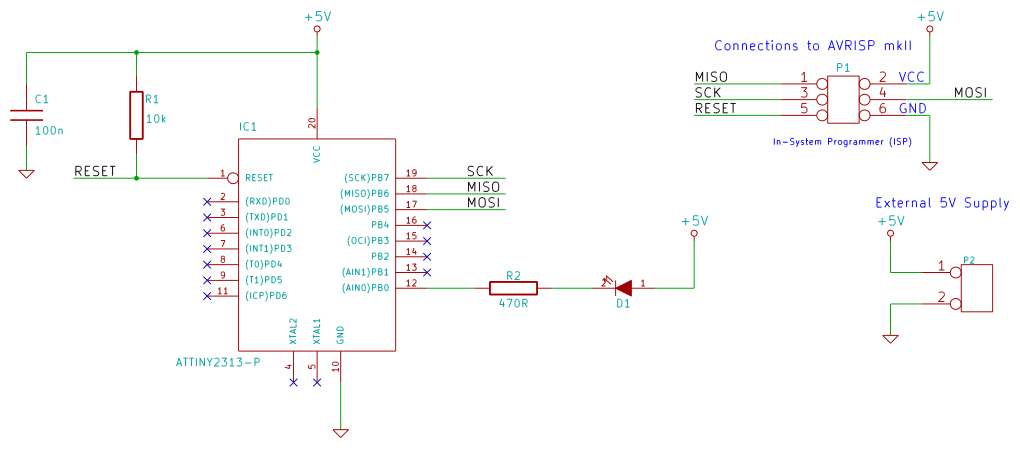
This tutorial examines the essential tools required for developing C programs on 8-bit AVR microcontrollers. It demonstrates how to write a C program and upload it to an AVR microcontroller, specifically utilizing an ATtiny2313 microcontroller breadboard circuit as a...

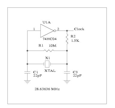
This HD TV UHF wideband amplifier (Ultra High Frequency amplifier) provides a total gain of 10 to 15 dB within the frequency range of 400 to 850 MHz, making it suitable for areas with weak television signals. To ensure...
When configured as an input, there is a subtle issue. If the input has its pull-up enabled, it may interfere with the circuitry that expects to see an analog-to-digital (A/D) input. Conversely, if the pull-up is not enabled, the...

This circuit utilizes a 4049 integrated circuit (IC) to control a 2N2222 switching transistor. The transistor, in turn, drives a piezo transducer known as crystal 1. The circuit design begins with the 4049 IC, which is a hex inverter capable...