
Vacuum Fluorescent Device Regenerative Receiver

The project involves constructing a regenerative receiver that utilizes a vacuum fluorescent display (VFD) as an alternative to traditional low-mu triodes. The regenerative receiver design employs a simple circuit architecture, incorporating a regenerative detector that amplifies radio signals. The "Spider" coil, known for its efficient inductance characteristics, is used to enhance the receiver's performance. The VFD serves as a functional substitute for the triode, effectively replicating the necessary electrode configuration while providing a modern twist to the retro design.
In terms of schematic representation, the regenerative receiver circuit includes the following components: a power supply that provides the necessary voltage to the VFD's filament and the anode; the Spider coil, which is connected to the input stage of the receiver; the VFD, where the control grid modulates the flow of electrons from the cathode to the anode; and output connections for audio signals that can be fed into a speaker or headphones. The VFD's phosphor-coated anodes are connected to a control circuit that enables the switching of different segments, allowing for visual feedback during operation.
The design emphasizes simplicity and accessibility, adhering to the principles of vintage radio construction while leveraging the functional attributes of modern display technology. The resulting receiver is expected to provide an engaging experience for both the builder and the user, showcasing the capabilities of regenerative receivers alongside the charm of retro electronics.This little project arose from a desire to experiment with some of the more "traditional" methods of radioconstruction which enjoyed popularity some 70 years ago. I wanted to find out for myself what kind of performance could be achieved using simple circuits incorporating Valves/Vacuum Tubes and low budget design techniques popular in the 1930`s.
In particular I was curious to try out "Spider" coils and a Regenerative Detector using a low-mu (low gain) triode as the active device. There is a great deal of "folklore" surrounding regenerative receivers with claims of exceptionally good performance from these simple designs.
For the most part these claims are well justified. Its true to say that a well constructed regen receiver of good design will give pleasing performance. Over the yearsa number of regen receivers have been constructed here at M0AYF for both broadcast and ham radio reception usingvacuum tubes and/or solid state devices.
Icanconfirm that they do indeed perform as advertised. But most of the receiversbuilt herehad taken advantage of using modern components and construction techniques so it was interesting to build the "retro" receiver using more traditional construction techniques and then to compare the performance to that of newer designs. In order to remain as faithful as possible to the traditional methods of construction and technology available in the 1930`s it was decided that low-mu (low gain) triodes would be used for the various stages of the receiver.
Though I have a small quantity of 1930`s triode valves/tubes in the M0AYF junk-box the decision was made to save these for a future "retro" project. So a suitableactive device to serve as a replacement for the low-mu triodes had to be found. Physical inspection of the internal construction of a VFD (Vacuum Fluorescent Device) revealed that it possessed all of the key electrodes found in a triode valve/tube.
A basic triode valve/tube consists of three electrodes, a heated cathode, a control grid and an anode/plate. The cathodeelectrode in a typical directly heated triode takes the form of a specially coated filament.
This coated filament is arranged such that when an electric current is passed through it the filament will heat up and "glow" causing electrons to be freely emitted. This is generally termeda "directly heated" or "self heated" cathode. Below is a cut-away diagram of a triode valve/tube which is of the directly heated type andtypical of those used in the 1930`s for domestic broadcast receivers.
A Vacuum Fluorescent Device (VFD) is a display device used extensively in domestic electrical goods such as VCR`s, bedside clocks and microwave ovens to name but a few. Though it may not be immediately obvious the internal construction of a VFD is very similar to that of a simple directly heated triode valve/tube, a sort of "Triode in Disguise".
The main difference is that the VFD isof a planar construction which is in contrast to the coaxial construction of the typical valve/tube shown in the diagram above. The VFD`s used in this project contain a single 7-segment display within a glass envelope and physically resemble a small valve/vacuum tube.
The VFD has a directly heated cathode (filament wires), a control grid and at least one anode/plate coated with a phosphor which emits light when struck by electrons. Most VFD`s have more than one phosphor coated anode/plate each with its own electrical connection to provide a multi segmented display.
For example a "numbers" display would typically have at least seven phosphor coated anodes/plates and possibly a few more to indicate the sign and decimal place. Theinternal electrodes of the the VFD device are shown in the diagram on the right. The phosphor coated anodes/plates have separate connections so that individual segments can be switched on or off to produce different numbers.
In the example VFD shown above the filament supply Voltage is ar 🔗 External reference
Related Circuits
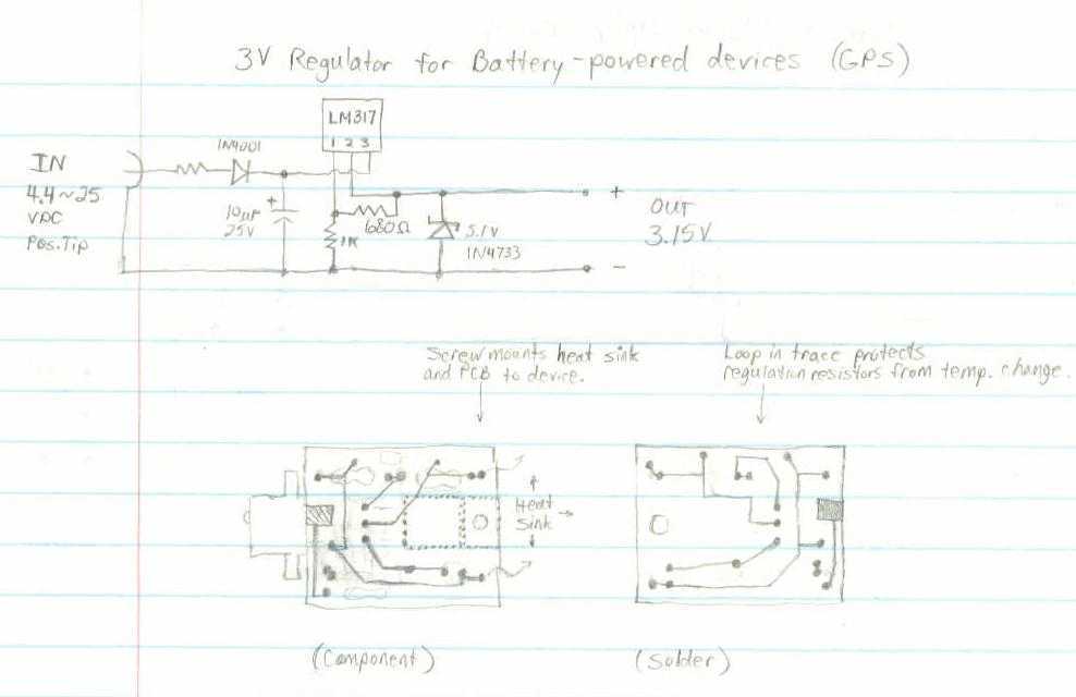
This GPS receiver is powered by 2 AA batteries. They are only strong enough for the GPS to stay on for about two hours, and this seems like quite a waste. I would like to be able to use...
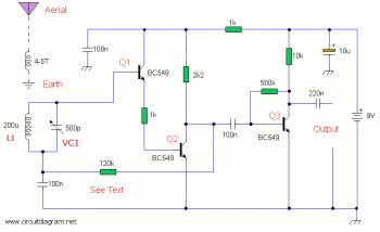
The AM radio receiver circuit diagram is based on the single integrated circuit MK484. The components list includes: R9, R10 (6.8 ohms), R6 (100 ohms), R3 (1k ohms), R1 (4.7k ohms), R7 (5.6k ohms), R4 (10k ohms), R2 (100k...
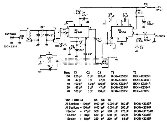
Note that T1 and T2 are TOKO components, including part numbers for the coils T1 and T2. The direct-conversion receiver shown utilizes a double-tuned input network made from readily available TOKO coils. IC1, an NE602, serves as a voltage-controlled...
This document outlines the hardware modifications required to adapt a Kenwood TK-931 transceiver for 902 MHz repeater receive operation. It does not include the programming effort needed for the desired operating frequency, which can be performed using Kenwood KPG-5D...
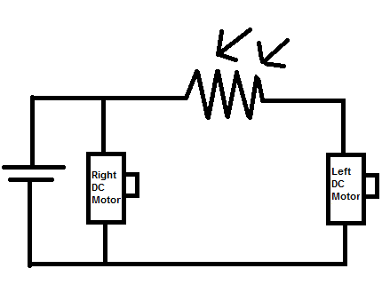
Construct a toy device that spins to the left whenever there is an obstruction in front of it, without utilizing a microcontroller. The proposed design involves using two DC motors as the rear wheels. An LDR (Light Dependent Resistor)...
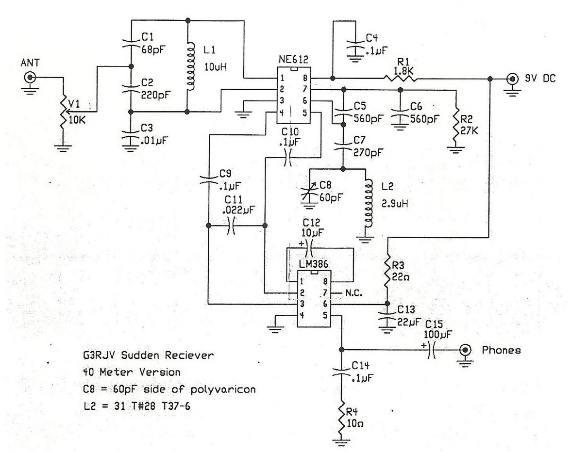
A straightforward direct conversion receiver utilizes the NE602 Gilbert Cell mixer and an LM386 audio amplifier. This circuit is inspired by the well-known sudden receiver design from Rev. George Dobbs, G3RJV. The implementation omits the tuned circuit components connected...