
Signals Logic Tester Circuit Using Display 7 Segment

The signal logic tester circuit operates by monitoring input signals and interpreting their logic levels. The common cathode seven-segment display is connected to a microcontroller or logic circuit that interprets the incoming signals. When the input signal is at a high logic level (logic "1"), the corresponding segment of the display illuminates to show an "H." Conversely, when the input signal is at a low logic level (logic "0"), the display shows an "L."
In the case of an undefined logic level, which may occur due to floating inputs or noise, the circuit is designed to provide a distinct visual cue. This could be achieved by illuminating a specific segment of the display or by activating an additional indicator, such as an LED, to alert the user that the signal is not within the expected range.
The circuit design typically includes a resistor network to limit current to the display segments and ensure proper operation. A microcontroller may be programmed to read the input levels and control the display outputs accordingly. The design may also incorporate debouncing techniques to filter out noise and provide stable readings.
Overall, this signal logic tester serves as a valuable tool for electronics engineers and technicians, allowing for quick and effective monitoring of digital signals in various applications.Here s a design of signals logic tester that is using indicate on a common cathode seven-segment display, if entry is at logic level ""1"" (one H on the display) or logic level (one L on the display). If an undefined level is detected will display .. 🔗 External reference
Related Circuits
Using modulated rectangular waves of different time periods, the circuit presented here produces ringing tones similar to those produced by a telephone. The circuit requires four astable multivibrators for its working. Therefore, two 556 ICs are used here. The...
The sensor operates on the principle that at high temperatures (200 to 800 °F), the temperature of the sensor varies with the thermal conductivity of gas, leading to changes in the resistance of the platinum resistor wire. In the...
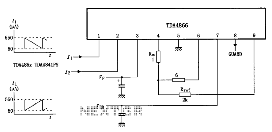
The TDA4866 test circuit operates with a positive supply voltage (VP) and a feedback voltage (VFB) in conjunction with a flyback circuit. The circuit responds to changes in the input signal, transitioning from one state to another. The input...
Testing loudspeakers is covered in some detail in the passive crossover article, but it is irksome at best to have to fiddle about with clip leads and components lying all over the workbench. This simple project is intended to...
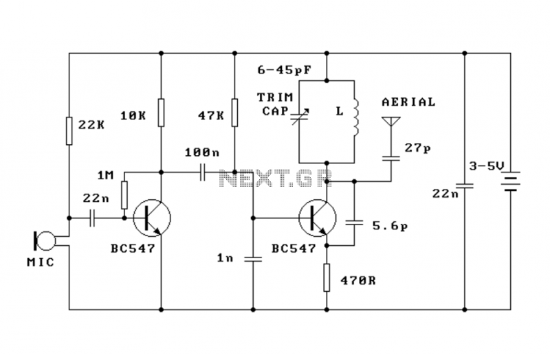
This FM transmitter (FM Tx) is about the simplest and most basic FM Tx it is possible to build and have a useful transmitting range. It is surprisingly powerful despite its small component count and 3V operating voltage. It...
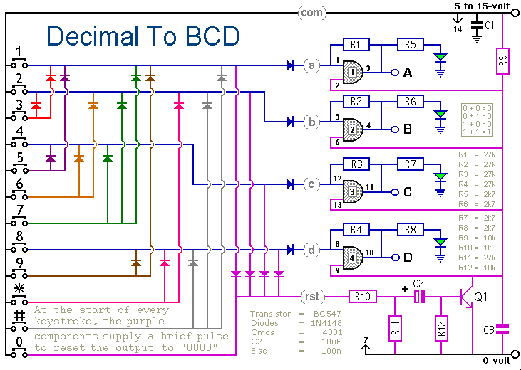
When a keypad switch is pressed, this circuit reproduces its value in Binary Coded Decimal (BCD) format. A 12-keypad is used, but it can be expanded to 16 keys for Hexadecimal to BCD conversion. The circuit consists of two...