
Varactor-tuned 10 mhz ceramic resonator oscillator

The described circuit employs a Field Effect Transistor (FET) input amplifier configured with fixed bias and source feedback to achieve high input impedance, which is essential for minimizing signal loading from preceding stages. The source feedback further enhances stability and linearity, crucial for maintaining signal integrity. The low capacitance characteristic of this amplifier allows for better high-frequency performance, making it suitable for applications requiring precise signal processing.
The output stage of the amplifier drives an emitter follower, which serves as a buffer. This configuration is advantageous due to the low output impedance of the emitter follower, enabling effective driving of subsequent circuitry without significant signal degradation. The transformer with a 3:1 turns ratio plays a critical role in impedance matching, allowing the circuit to interface effectively with the ceramic resonator, which operates at very low impedance levels.
The use of a varactor-tuned ceramic resonator oscillator introduces the ability to adjust the frequency of oscillation based on the applied voltage, which is particularly beneficial in applications such as frequency modulation or signal generation. The significant frequency-temperature coefficient indicates that the oscillation frequency will vary with temperature changes, a critical aspect to consider in design and operational conditions. The tuning range of approximately 232 kHz provides flexibility, although the temperature coefficient of -350 Hz per degree Celsius necessitates careful management of the tuning range to ensure reliable operation.
It is important to note that when the circuit is utilized as a VCO, the full tuning range cannot be exploited due to the inherent temperature dependence. This limitation requires the designer to allocate part of the tuning range to account for temperature variations, thereby impacting the overall performance of the VCO. In scenarios where a specific tuning range of 200 kHz is required, the sacrifice of 32 kHz for temperature compensation results in significant thermal drift, which must be addressed to maintain accurate frequency output. This necessitates additional thermal management strategies or compensation techniques in the design to ensure stable operation across varying environmental conditions.The FET input amplifier has fixed bias with source feedback. This provides a very high input impedance with very low capacitance. The FET amplifier drives an emitter follower which, in spite of the fact that it has a low output impedance, feeds a transformer with a 3:1 turns ratio for a nine-fold impedance reduction. The result is an impedance at the ceramic resonator of a few ohms maximum. The varactor-tuned ceramic resonator oscillator has a significant frequency-temperature coefficient. The tuning range of the VCO is approximately 232 kHz, with a temperature coefficient of-350 Hz per degree centigrade.
When using this circuit as a VCO, the entire 232 kHz range cannot be used because some of the tuning range must be sacrificed for the temperature dependence. If the required tuning range were 200 kHz, leaving 32 kHz for temperature variation, the resulting temperature variation would be more than 90°C.
Related Circuits
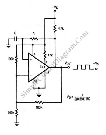
This is an astable multivibrator (oscillator) circuit utilizing a CMOS inverter. The circuit employs the CD4007 or MC14007 components. It operates within a frequency range of... The astable multivibrator circuit is designed to generate a continuous square wave output without...
The circuit depicted in this schematic diagram is a square-wave oscillator circuit. The primary component of this oscillator circuit is the LP165/365 comparator. The square-wave oscillator circuit utilizes the LP165/365 comparator to generate a continuous square wave output. The...
Zener diodes were utilized to derive a stabilized voltage for the Hartley oscillator. While sorting through a box of valves, suitable voltage stabilizer valves (CV287) were discovered. During this process, the ECC81 utilized in the local oscillator was noted...
The RF engineer occasionally needs to find an instrument that can reliably and quickly test a low-frequency quartz crystal unit. This equipment is often challenging to locate, leading engineers to consult electronic circuits handbooks for schematics that can perform...

This circuit represents a negative resistance configuration. All previous circuits utilize RC time constants to achieve resonance. LC combinations can also be employed, providing good frequency stability, high Q factor, and rapid startup. In this circuit, a signal input...
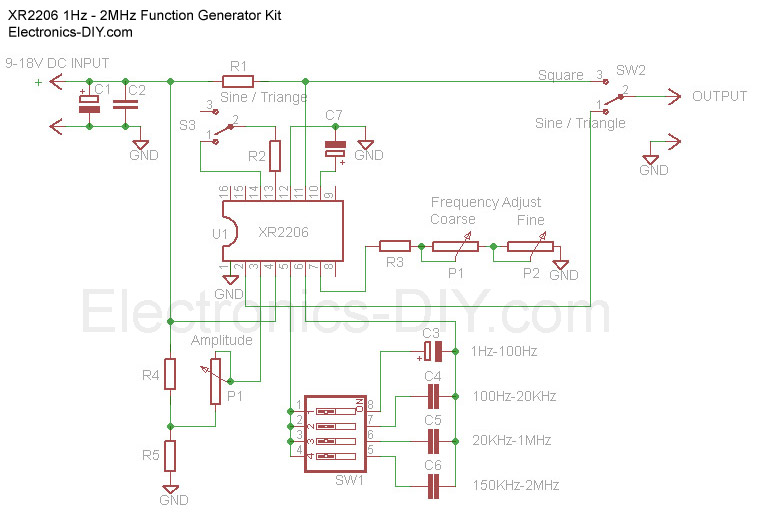
The Function Generator is essential laboratory equipment. The module described here is based on the high-quality XR2206 integrated circuit (IC). The 1Hz - 2MHz XR2206 Function Generator is capable of producing high-quality sine, square, and triangle waveforms with high...