
variable 0 to 300 volts regulated power

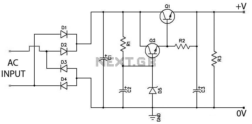
The power supply circuit operates by converting the alternating current (AC) from the mains into a direct current (DC) output through a bridge rectifier configuration. The bridge rectifier consists of four diodes arranged in a specific manner to allow current to flow in one direction, effectively converting AC to DC. The output of the bridge rectifier is then smoothed using a 10µF capacitor rated at 400 volts, which reduces voltage ripple and stabilizes the output voltage.
For the voltage adjustment feature, a variable resistor or potentiometer may be integrated into the circuit. This component allows the user to set the desired output voltage by varying the resistance, thereby controlling the voltage drop across the load. The circuit may also include an operational amplifier configured as a voltage follower to ensure a stable output voltage regardless of load variations.
Due to the high voltage capabilities of this power supply, all components must be rated appropriately to handle the maximum voltage and current. Heatsinks are essential for components that dissipate significant power, such as voltage regulators or transistors, to prevent overheating and ensure reliable operation.
Safety precautions are critical when working with high voltages. It is advisable to include fuses or circuit breakers to protect against overcurrent conditions, as well as proper insulation and enclosures to prevent accidental contact with live parts. Additionally, incorporating a voltmeter and ammeter can provide real-time monitoring of the output voltage and current, enhancing the usability of the power supply.
This design offers versatility for various applications, such as testing electronic components, powering high-voltage devices, or conducting experiments requiring a wide range of voltage outputs. Proper assembly and adherence to safety standards will yield a robust and reliable high-voltage power supply.This power supply can be used to obtain a regulated power output, variable right from zero to 300 volts maximum. All the devices should be mounted on heatsinks. You must havecome across many power supply circuits which are designed for supplying anywhere between 0 to 25 or at the most 40 volts DC, but the circuit presented here will give you
a robust power right from 0 to 300volts continuously variable. The input to the circuit may be derived directly from the mains AC after proper rectification and filtration using a bridge network and a 10u/400V capacitor. 🔗 External reference
Related Circuits
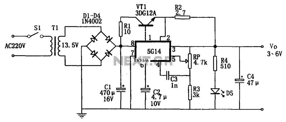
As shown in the figures, this is a practical adjustable power supply. It utilizes an integrated voltage regulator (5G14) in conjunction with a 3DG12A transistor for current spreading, providing an output voltage range of 3 to 6V. The rated...
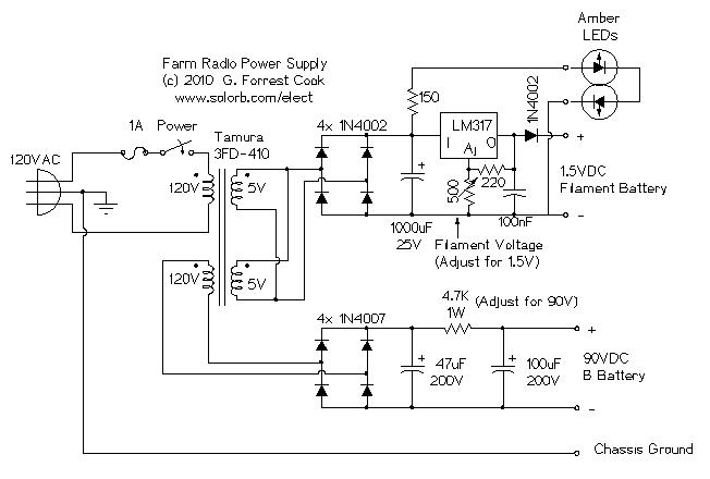
The ability accumulation is a Tamura 3FD-410 5V bifold primary/dual accessory transformer, available from DigiKey.com at reasonable prices. The transformer's primary windings can be configured in series for 240VAC operation or in parallel for 120VAC operation. This configuration utilizes...
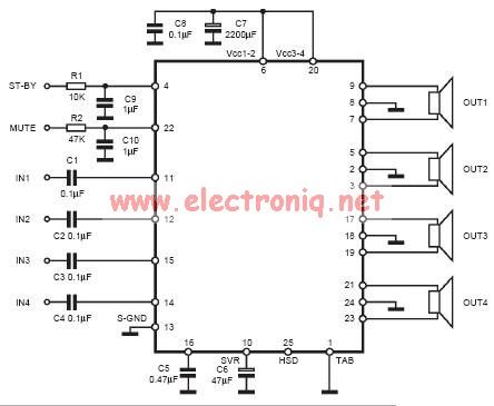
The input capacitor is used for low-frequency cut-off, with a standard value of 0.1 µF, resulting in a cut-off frequency of approximately 16 Hz. The input capacitor plays a crucial role in filtering unwanted low-frequency signals in electronic circuits. By...
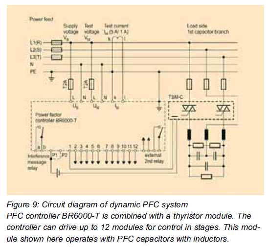
A change in technology is occurring in power factor correction. Static power factor correction (PFC) systems are being gradually replaced by dynamic systems that provide new technical advantages. Dynamic power factor correction (PFC) systems represent a significant advancement in managing...
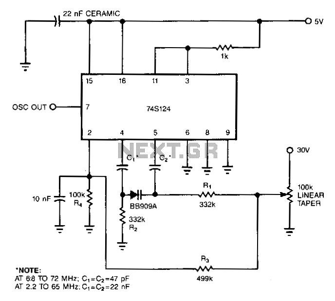
A 7415124 multivibrator can be converted into a wideband voltage-controlled oscillator (VCO) by substituting the conventional fixed capacitor with a variable-capacitance diode. The primary drawback of this configuration is the 30-V biasing voltage required by the diode. Capacitors C1...
Low Ripple Regulated Power Supply Circuit Diagram. This circuit can be employed in applications requiring high current with minimal ripple voltage, such as in high-powered class AB amplifiers where high-quality audio reproduction is essential. The low ripple regulated power...