
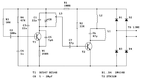
Variable charger circuit Schematic Diagram

The accumulator charger circuit is designed to deliver precise voltage levels suitable for charging batteries, particularly 12-volt models. The key component of this circuit is a voltage regulator, which stabilizes the output voltage and prevents it from exceeding the battery's rated voltage. This is crucial as overcharging can lead to battery degradation or failure.
The circuit typically consists of a transformer that steps down the mains voltage to a lower AC voltage suitable for charging. This AC voltage is then rectified using diodes to convert it into DC voltage. A smoothing capacitor may be used to reduce voltage ripple, providing a more stable DC output. The voltage regulator, which can be a linear regulator or a switching regulator, ensures that the output remains within the safe charging range for the accumulator.
Additionally, a feedback mechanism is often implemented to monitor the output voltage continuously. This feedback loop allows for dynamic adjustments to the regulator, maintaining the output voltage at the desired level. Some designs may incorporate an LED indicator to signal when the charger is active and functioning correctly.
Safety features such as fuses or circuit breakers may also be included to protect against overcurrent conditions, while thermal protection mechanisms can prevent overheating of components. Overall, the accumulator charger circuit is a critical component in battery management systems, ensuring longevity and reliability of rechargeable batteries.Indeed the accu charger circuit, the voltage required must be in accordance with voltage batteries, such accu 12 volts the the output voltage should not be above 12 volts and 12 volts should not be too down. If it does not comply with the required voltage, it will make the batteries or accu quickly broken. But not to worry to find the right vol tage to charge to accu, the voltage control circuit is equipped to facilitate in determining the voltage. 🔗 External reference
Related Circuits
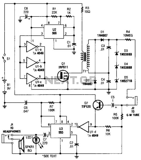
The circuit is constructed using a 4049 hex inverter (U1), two 555 oscillator/timers (U2 and U3), two transistors, a Geiger-Muller tube, and several additional support components. The first 555 timer (U2) is set up for astable operation. The output...
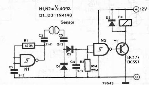
The liquid detector is a device designed to detect the presence of liquid using alternating voltage. This circuit can be constructed using common electronic components. The alternating voltage is generated by a gate with a Schmitt trigger function, acting...
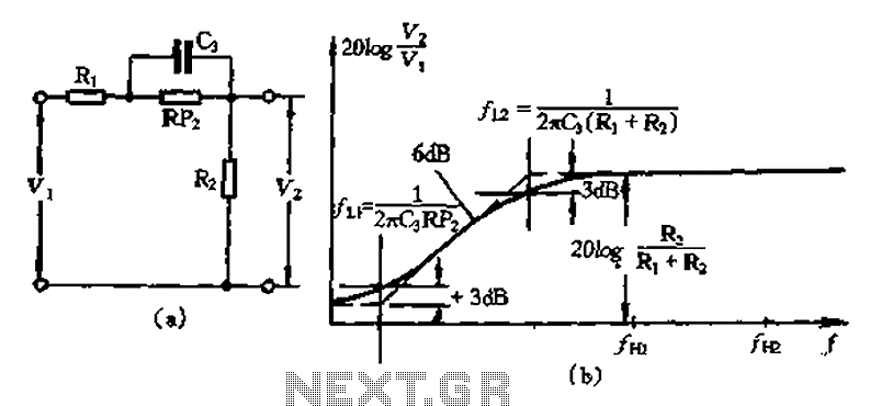
There are two corner frequencies present: the start frequency attenuation transition is defined by several parameters, including F1/27rC3 (Ri + R2). This is followed by a decay into a flat corner frequency, denoted as LI, which is represented by...
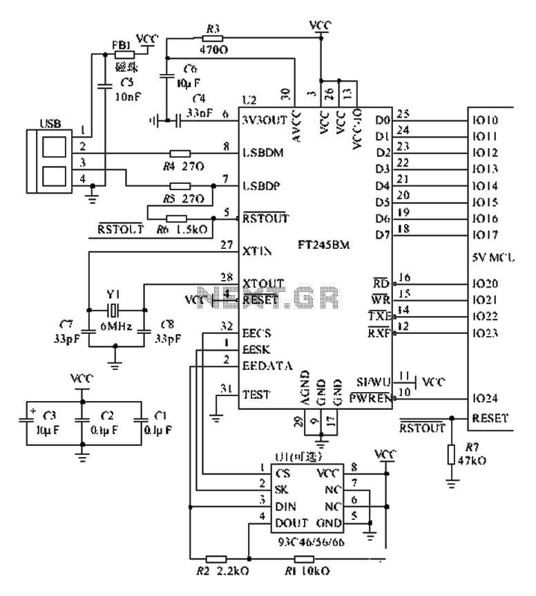
The FT245BM typical hardware circuit operates in bus-powered mode and employs a power-on reset mechanism to initialize the device. The clock circuit can be implemented using a 6 MHz crystal oscillator module or a combination of a 6 MHz...
The tone generator was a straightforward project developed as a test unit for a customer design job. It utilizes two analog switches controlled by microprocessor code: one switch manages the signal directed to the operational amplifier that drives the...
This FM spy telephone circuit is connected in series with the phone line. When there is a signal on the wires, this transmitter will radiate airwaves through the wires. This FM spy telephone circuit operates by integrating with the existing...