
Variable DC Power Supply Circuit

The Variable DC Power Supply circuit typically utilizes a linear voltage regulator or a switching regulator to achieve the desired output voltage and current. The primary components include a transformer, rectifier, filter capacitor, adjustable voltage regulator, and current limiting resistor.
The transformer steps down the AC mains voltage to a lower AC voltage suitable for the application. The rectifier, often a bridge rectifier configuration, converts the AC voltage to pulsating DC. Following the rectification, a filter capacitor smooths the output voltage, reducing ripple and providing a more stable DC output.
The adjustable voltage regulator, such as the LM317 or a similar device, allows for the output voltage to be varied by using external resistors to set the desired voltage level. The current limiting feature can be implemented by adding a resistor in series with the load or by utilizing a current sensing circuit that adjusts the output voltage when the load current exceeds the specified limit.
The design should include adequate heat sinking for the voltage regulator to prevent overheating during operation, especially when operating at higher currents. Additionally, incorporating a digital voltmeter and ammeter can provide real-time monitoring of the output voltage and current, enhancing usability.
Overall, this Variable DC Power Supply design is adaptable, allowing hobbyists to modify it according to specific needs while ensuring safety and reliability in various electronic projects.A Variable DC Power Supply is one of the most useful tools on the electronics hobbyist`s workbench. This circuit is not an absolute novelty, but it`s simple, reliable, "rugged" and short-proof, featuring variable voltage up to 24V and variable current limiting up to 2A. It`s well suited to supply the circuits shown in this website. You can adapt i t to your own requirements as explained in the notes below. 🔗 External reference
Related Circuits
The circuit described below is notable for its low power consumption. With a 9V input and no load at the output, it draws only 50 mA, which is significantly lower than the quiescent current of a 78L05 regulator. The...
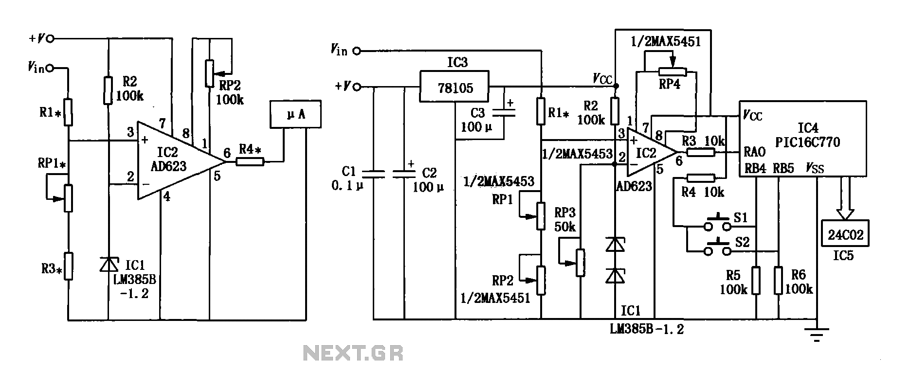
The range precision voltmeter electrical schematic is depicted in Figure (a) below. It features an amplifier circuit and several high-precision components that significantly enhance the performance range of the voltmeter. The inverting input of the instrumentation amplifier AD623 (IC2)...
The circuit operates on the principle of detecting smoke produced during a fire. Smoke reduces the amount of light reaching a Light Dependent Resistor (LDR) placed between a light bulb and the LDR. This configuration is known as an...

This light-sensitive circuit can operate a relay to switch on lamps or any AC loads when it detects darkness. It is ideal for use as a switchless night lamp. The circuit utilizes a light-dependent resistor (LDR) as its primary sensing element....
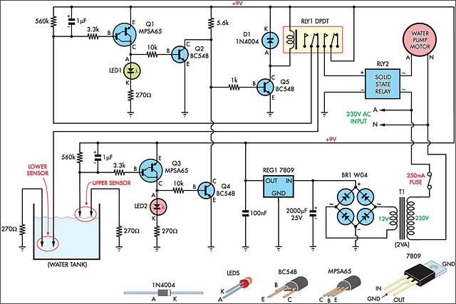
This circuit is designed to effectively fill a header tank for a reticulated water supply on a farm. It supports eight troughs located in various paddocks, where inadequate water supply can have serious repercussions for livestock. Previously, a timer-based...
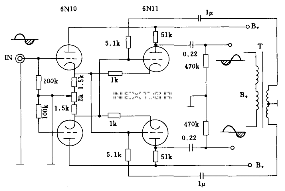
Balanced cross tube inverter circuit, also known as the Chelles inverter circuit, can be utilized as a preamplifier and employs 6N10 and 611 tubes in an inverted configuration. The circuit is designed to work with a final amplifier tube, specifically...