
Variable PIN Attenuator

The RF attenuator circuit described employs a quad PIN diode array, specifically the HSMP-3816, which is known for its low insertion loss and high linearity in RF applications. The configuration includes two stages of diodes: the lower diodes, which are consistently biased at 1 mA, provide a stable impedance that is crucial for maintaining signal integrity across the specified frequency range. By adjusting resistor R5, users can fine-tune the input and output impedance to match the requirements of the RF system, ensuring optimal performance and minimizing reflections.
The upper diodes are influenced by a control voltage that can be varied from 0 to 10 V. At 0 V, the diodes enter a high-resistance state, effectively blocking the RF signal. As the control voltage increases, the diodes transition to a low-resistance state, allowing the RF signal to pass through with minimal attenuation. This feature is particularly advantageous in applications requiring dynamic control of RF signals, such as in communication systems or signal processing.
The design also highlights the efficiency of using a small control current to manage a higher power RF waveform, making this circuit suitable for integration into various RF applications where space and power efficiency are paramount. Overall, this RF attenuator circuit demonstrates significant utility in modern electronic design, particularly in systems that require precise control over signal levels.This is a very useful RF attenuator circuit which works from 300KHz to the 3GHz range based on the quad PIN diode array HSMP-3816 from Avego. The lower PIN diodes are biased at 1mA which gives about a 40 to 70 ohm impedance. R5 can be increased to increase the RF input and output impedances of the circuit. The upper diodes are biased by the contro l voltage which varies between 0 and 10V. The signal is essentially blocked when the control voltage is 0V and passes when the control voltage is high. The beauty of this circuit is that a small current can control a higher power RF waveform. Do you need help with an electronics design Daycounter provides contract electronics design services.
Contact us to give you a quote on your electronics design project. 🔗 External reference
Related Circuits
This circuit is not entirely new, but it is straightforward, dependable, robust, and short-proof. It offers variable voltage up to 24V and adjustable current limiting up to 2A. Customization to meet specific requirements is possible, as detailed in the...
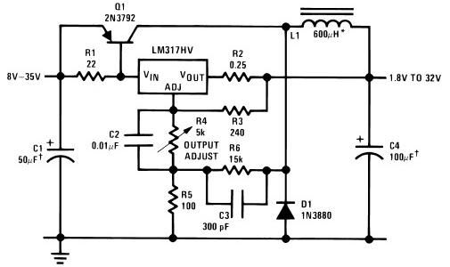
The circuit diagram of this LM317 power supply electronic project requires a few external components. The input voltage for this project must be between 8 and 35 volts, providing a variable output voltage ranging from 1.8 volts to 32...
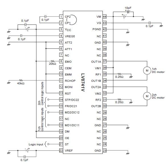
The circuit diagram illustrates an electronic project that requires a few external electronic components. The PWM current-control stepping motor driver IC can provide a maximum output current of up to 1.5 amperes. The configuration settings for the PWM current-control...
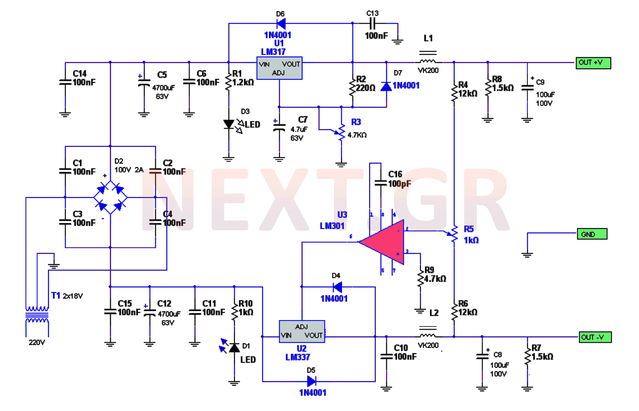
The power supply circuitry includes a 220/2 * 18V / 3.5A transformer, a rectifier, a smoothing filter, a power amplifier (LM301), and two regulators (LM317 and LM337). The voltage from the transformer is rectified by a bridge rectifier. Capacitors...
I have received countless emails asking for a circuit to tell the user which car won in a pine car (also called Pinewood Derby, Cub Car, Scout Car, etc.) race. This simple circuit takes care of the guesswork, lighting...
In older amps is usually a phono input. Today, this used less and less, and it would be useful if the input and line input can be used. This circuit goes. The circuit is actually an attenuator and a...