
Transistor current limit circuit power handling

The circuit design involves a current limiting mechanism that ensures safe charging of the large capacitor while preventing excessive power dissipation in the transistors. The charging process begins when the supply voltage is applied, allowing the capacitor to charge at a controlled rate. The current limiter is primarily achieved through the use of the MMBT2222A transistor, which operates in its active region to regulate the current flowing into the capacitor.
To enhance the current handling capability, the additional 2N2222A transistor is introduced in parallel with the MMBT2222A. This configuration aims to distribute the total load current between the two transistors. However, careful consideration must be given to the characteristics of the transistors, as differences in current gain (hFE) can lead to unequal current sharing. To mitigate this risk, it is advisable to use resistors in series with the base of each transistor, which can help balance the base currents and improve current sharing.
The circuit also requires a robust design to manage the initial inrush current when the capacitor is charged. During this phase, the voltage across the collector can reach significant levels, necessitating the use of transistors that can withstand higher power dissipation. It may be beneficial to implement thermal management strategies, such as heat sinks, to prevent overheating of the transistors during operation.
In summary, the design of this current limiter circuit emphasizes the importance of careful component selection and configuration to ensure reliable performance. The use of the MMBT2222A and 2N2222A transistors in parallel presents both opportunities and challenges, requiring a thorough understanding of their characteristics and behavior under load conditions. The overall goal is to achieve a safe and effective charging mechanism for the large capacitor while minimizing the risk of component failure due to excessive power dissipation.Designing a simple current limiter, which charges a large (4. 7mF) capacitor with a charge current of (roughly) 500mA from a supply voltage from about 10-20V - see the below circuit. My dilemma is that I already have a bunch of MMBT2222A and it would be nice to use this part without another line item.
Whilst it can happily push 500mA through t he collector, it only has a power rating of 350mW, which will be massively exceeded when the capacitor is first charged as the voltage across the collector will be about 10V and hence the power will be about 5W for the first 200ms or so. In the circuit above, I have added an extra 2N2222A in parallel (with the idea of adding more as required) with the existing one, but I feel this strategy if fraught with danger - mismatched gains will cause unequal currents and defeat the whole purpose of the exercise.
🔗 External reference
Related Circuits
The variable frequency power supply is a crucial component of the power system, as its characteristics significantly impact the security and reliability of the overall system. The modern variable frequency power supply is characterized by low power consumption and...
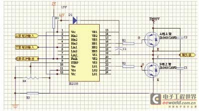
The 555 timer on the right is configured as an alarm sound generator, while the second 555 timer on the left functions as a 1 Hz astable multivibrator. The output from the left timer modulates the frequency of the...
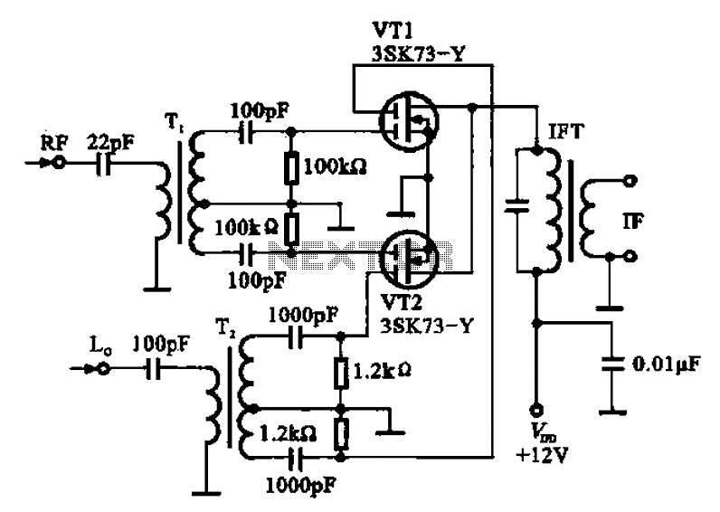
A balanced mixer circuit is illustrated using two dual-gate field effect transistors (FETs). The RF signal is coupled to the gates of these transistors through an input signal transformer (T1). Additionally, a local oscillation signal is introduced to the...
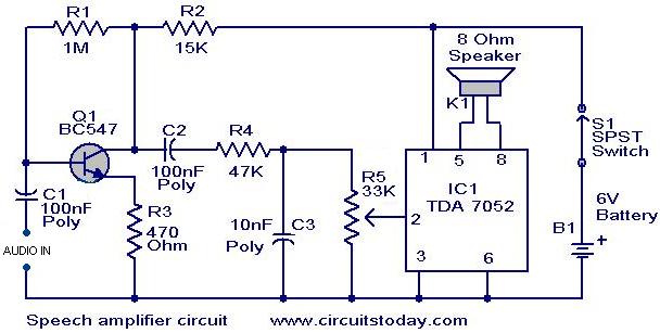
This circuit can be housed within a box containing a speaker to create a convenient microphone amplifier. It is suitable for use by teachers, guides, lecturers, and others in crowded or noisy environments. The design is based on the...

The following circuit illustrates an Automatic Loudness Control Circuit Schematic. This circuit is based on the TL072 integrated circuit. Features include various functionalities. The Automatic Loudness Control Circuit is designed to adjust audio signal levels dynamically, enhancing the listening experience...

Most thefts occur after midnight when individuals enter the second phase of sleep known as 'paradoxical sleep.' Here is an energy-saving circuit that causes... An energy-saving circuit designed for security applications can be particularly beneficial during the late-night hours when...