
Variable Q Filter For 400Hz Circuit

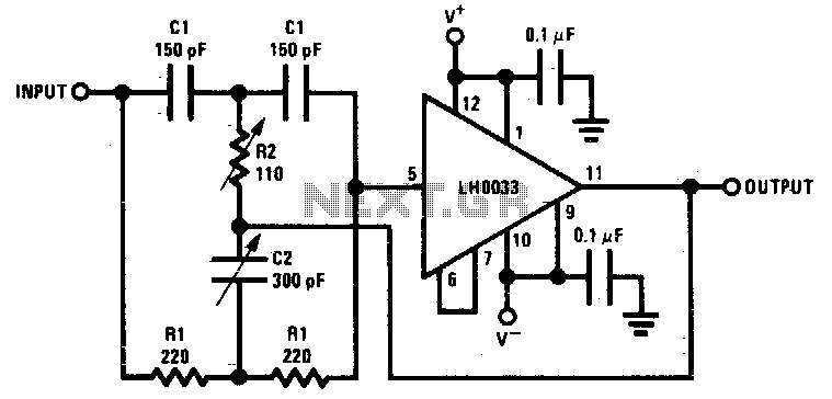
The bootstrapped twin notch filter is a sophisticated circuit configuration designed to achieve high selectivity and precision in filtering specific frequency components from a signal. The effective quality factor (Q) of up to 10 indicates the circuit's ability to provide sharp frequency discrimination, which is essential in applications such as audio processing, communications, and instrumentation.
In this circuit, the resistor Rs plays a crucial role in adjusting the feedback loop, thereby influencing the overall Q factor of the filter. By modifying Rs, the feedback level can be tuned, allowing for precise control over the filter's response characteristics. This adaptability is particularly beneficial in scenarios where the frequency response needs to be optimized for different signal conditions.
Capacitors C1 and C2 are integral to determining the filter's center frequency. By selecting appropriate values for these capacitors, the user can effectively shift the notch frequency to target specific unwanted frequencies within the signal spectrum. This feature enhances the filter's versatility, making it suitable for various applications requiring frequency manipulation.
The RF component serves as a fine-tune null control, providing additional adjustment capabilities to achieve the desired notch depth and position. This control allows for meticulous calibration, ensuring that the filter operates optimally in its intended application.
When designing this circuit, careful consideration should be given to the selection of components to maintain stability and performance across varying operating conditions. Proper layout and grounding techniques are also essential to minimize noise and interference, further enhancing the filter's effectiveness. Overall, the bootstrapped twin notch filter represents a powerful tool for precise frequency management in electronic systems. A bootstrapped twin notch filter in this circuit can yield an effective Q of up to 10. Rs adjusts the feedback, hence the Q. Values of C1 and C2 can be changed to alter the frequency. RF is a fine-tune null control.
Related Circuits
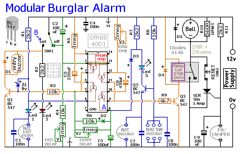
This circuit includes automatic exit and entry delays, as well as a timed bell cut-off feature. It supports both normally-closed and normally-open contacts, and incorporates a 24-hour personal attack/tamper zone. The use of expansion modules allows for the addition...
A sawtooth wave generator circuit using a 555 IC is presented in the article below. The frequency equation is provided with the supply voltage Vcc. The sawtooth wave generator circuit utilizing a 555 timer integrated circuit (IC) is a fundamental...
Component value sensitivity is extremely critical, as are temperature coefficients and matching of the components. Best performance is attained when perfectly matched components are used and when the gain of the amplifier is unity. To illustrate, the quality factor...
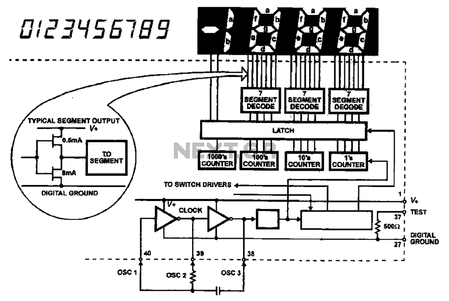
The AC input circuit functions as a converter, transforming an alternating current (AC) signal into a direct current (DC) signal, which is subsequently processed by an analog-to-digital (A/D) converter chip. The input circuit is designed to handle AC signals, typically...
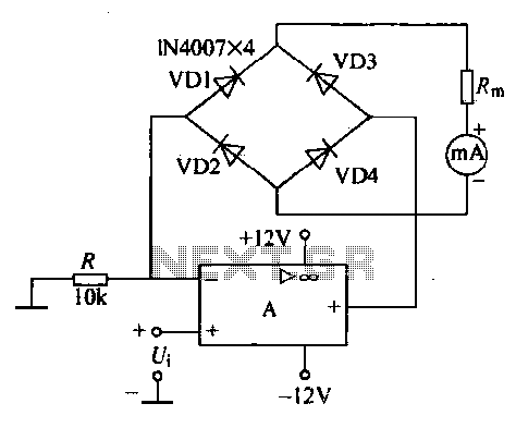
An operational amplifier, a diode bridge rectifier, and DC mA AC voltmeter tables are illustrated in the figure. The operational amplifier used is the LM324. The measured AC voltage is applied to the inverting terminal of the operational amplifier,...
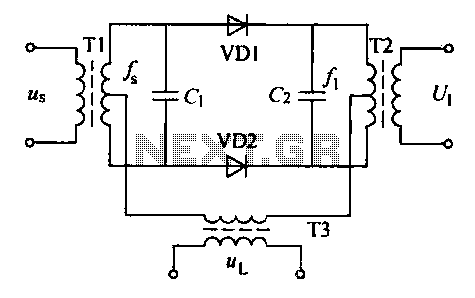
A balanced diode mixer circuit is presented, utilizing two diodes, specifically the 2AP9 model. The circuit operates with a high voltage, causing the diodes to function in an off state, which is also referred to as a diode switch...