
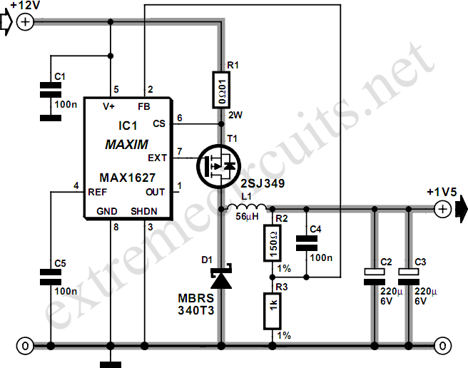
variable step up dc dc converter 2

The circuit in question involves a transformer that converts high-voltage AC to a lower voltage level suitable for further processing. When considering the use of a 240VAC-12VAC transformer, it is essential to ensure that the primary and secondary voltage ratings align with the requirements of the circuit. The primary winding must be rated for 117VAC, while the secondary winding should provide 6.3VAC center-tapped output.
In practical applications, the selection of the drive frequency is crucial for maximizing transformer efficiency. The transformer operates optimally at a specific frequency, which can be determined through experimentation. By loading the transformer with a variable resistor and measuring the output across this load, the relationship between frequency, output voltage, and input current can be analyzed.
The ripple voltage is a critical parameter in the design of power supply circuits. In this case, a ripple of +/-25V at output voltages greater than 200V indicates that the output is not a smooth DC, but rather exhibits significant fluctuations. The waveform characteristics, described as spikes followed by a decay, suggest that additional filtering may be required to smooth the output voltage if a stable DC supply is necessary for subsequent circuit stages.
Overall, careful consideration must be given to transformer specifications, drive frequency, and output characteristics to ensure reliable operation in the intended application.Might be a stupid quiestion but as 240vac-12vac transformers are readily available (and are roughly the same scale) could i use one of these in the circuit instead If the specific transformer mentioned in the schematic is not available to you, any transformer with the specifications primary 117VAC, secondary 6. 3VAC CT (center-tapped) should work. In this case you might have to choose a different drive frequency in order to operate at the sweet spot of the transformer: "[. ] I found in driving a transformer as is done in this project that the overall performance varied significantly as I varied the drive frequency.
In a series of experiments I loaded the transformer directly with a variable resistor (no rectifier used), measured the AC voltage across this resistor, measured the DC current into the transformer, and varied the drive frequency. I looked for a frequency where the output voltage was highest and the input current was lowest. [. ] `ripple` is roughly +/-25V for output voltage >200V. This ripple isn`t sinusoidal at all. It is basically a spike then monotonically decays until the next spike. " 🔗 External reference
Related Circuits
To sense and control the current in stepping motors and other similar devices, a linear integrated circuit such as the L6506 can be utilized. This chip set enables the formation of a constant current output. The L6506 is a versatile...
Most small internal combustion engines used in model building utilize glow plugs for starting. However, glow plugs operate at 1.5 V, while components like fuel pumps, starter motors, and chargers typically operate at 12 V. This discrepancy necessitates a...
The circuit illustrates a method to obtain a voltage of 90V from a 1.5V battery supply. The LT1073 switching regulator from Linear Technology operates in boost mode and can function with an input voltage as low as 1.0V. The...
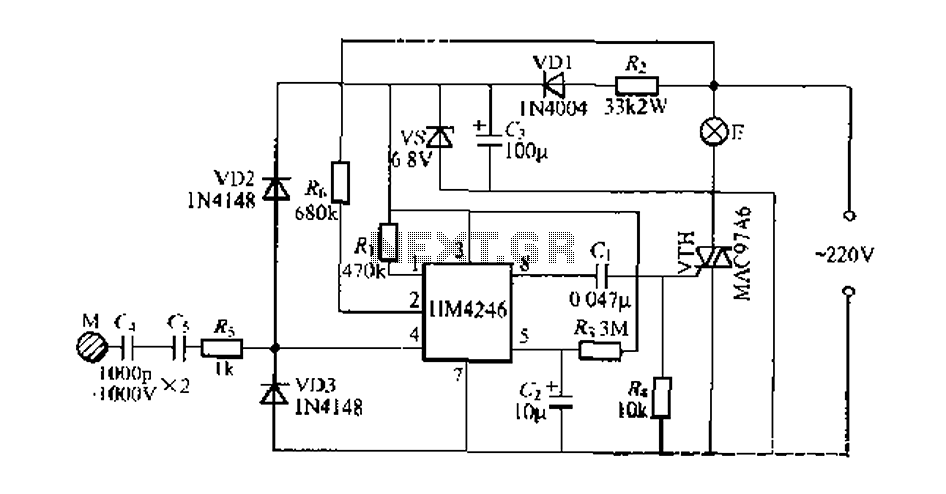
Development and production of a specialized touch dimmer integrated circuit. This circuit features four lighting functions: dark, medium, light, and a touch-sensitive trigger on all four sides. It has low harmonic radiation emission, high touch sensitivity, and stability. It...
Any stepper motor can function as a generator. Unlike other types of generators, a stepper motor generates a significant induced voltage even at low rotational speeds. The specific model used here has a DC resistance ranging from 2 ohms...
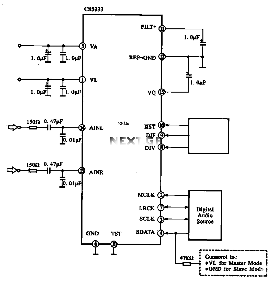
Audio A/D converter circuit configuration using the CS5333 chip, which is a high-performance 24-bit, 96 kHz stereo A/D converter commonly used in digital products. This circuit converts one or more audio signals into a digital signal for processing and...