
Variable Voltage Regulator

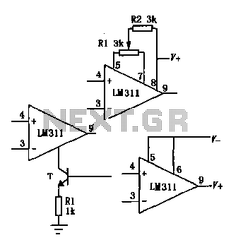
The described circuit utilizes an operational amplifier in a non-inverting configuration, which is a popular choice for applications requiring signal amplification without phase inversion. The gain of the amplifier is set by the feedback resistors R3 and R2, following the formula \( \text{Gain} = 1 + \frac{R3}{R2} \). This allows for precise control over the amplification factor, making it versatile for different applications.
The input voltage is adjustable between 0 and 15 V through resistor R5, which serves as a variable resistor (potentiometer) in the circuit. This feature enables the user to tailor the input signal level according to the requirements of the specific application. The output voltage range of approximately 0.5 to 30 V suggests that the op amp is capable of amplifying the input signal significantly, depending on the gain setting.
To enhance the output current capability, which is often limited in standard op amp configurations, a transistor (Q1) has been added to the output stage. This transistor acts as a current booster, allowing the circuit to drive larger loads without compromising performance. The transistor is likely configured in a common-emitter or emitter-follower arrangement, depending on the desired output characteristics and load requirements.
Overall, this circuit configuration is suitable for various applications, including sensor signal conditioning, audio amplification, and other scenarios where a stable and adjustable DC voltage output is necessary. The careful selection of components and configuration ensures reliable performance across the specified input voltage range. The op amp is wired as a 2 noninverting dc amplifier with a gain that is determined by the R3/R2 ratio. The inp ut voltage to the op amp is variable between 0 and 15 V via R5. The output voltage is therefore variable over the approximate range from 0.5 to 30 V. The available output current has been boosted by adding transistor Ql to the output.
Related Circuits
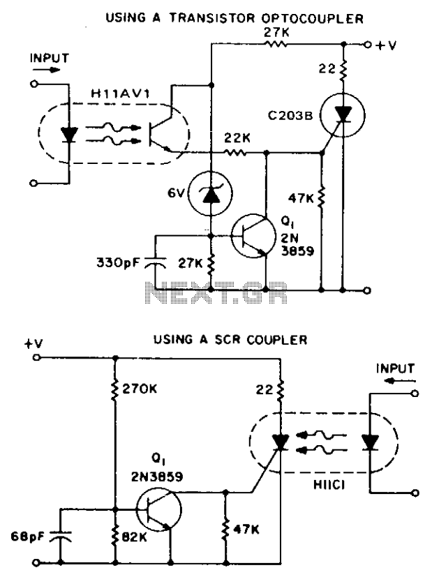
These two simple circuits provide zero voltage switching. They can be used with full wave bridges or in antiparallel to provide full wave control and are normally used to trigger power thyristors. If an input signal is present during...
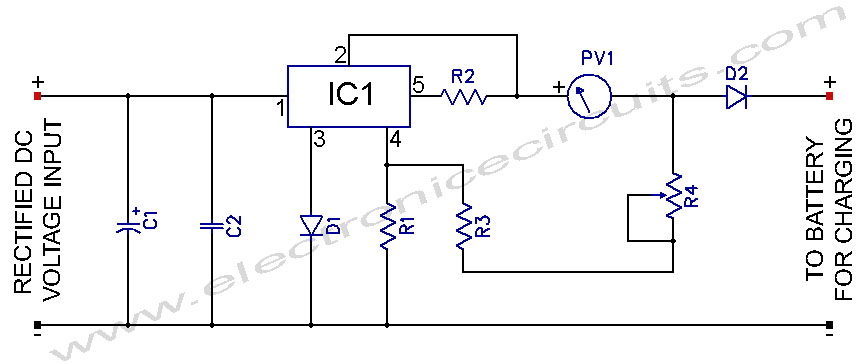
L200 12V Constant Voltage Battery Charger Circuit. This battery charger is based on the L200 regulator IC. The L200 is a five-pin adjustable voltage regulator. The L200 constant voltage battery charger circuit is designed to provide a stable 12V output...
This circuit is not a novelty, but it proved so useful, simple and cheap that it is worth building. When the positive (Red) probe is connected to a DC positive voltage and the Black probe to the negative, the...
The LM111/211/311 power supply operates within a voltage range of 5V to 15V. It features bias current, offset current, and a differential input voltage range of 30V. The output is compatible with TTL, DTL, and MOS circuits, allowing it...
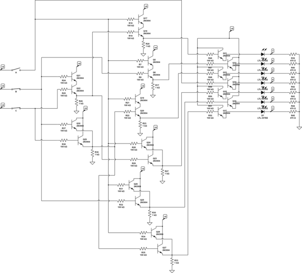
There are three switches that represent a binary number, and according to the combination of those switches, the number of lit LEDs changes to represent that binary number. There is a question regarding how to provide equal current and...
The hobby circuit described can be connected to a 3V battery to provide a warning when the battery is nearing its end of life. It will flash an LED when the battery voltage drops to approximately 2.4 volts. The...