
varying brightness ac lamp

This circuit employs a Silicon Controlled Rectifier (SCR) to modulate the power delivered to a 120-volt incandescent light bulb. The SCR is a semiconductor device that functions as a switch, allowing control over the AC voltage applied to the load. The operation of the SCR is based on phase control, where the triggering of the SCR is delayed within each half-cycle of the AC waveform.
The circuit typically consists of the following components: an SCR, a resistive load (the light bulb), a variable resistor or potentiometer for adjusting the phase angle, and a diode for protection against reverse voltage. The variable resistor is connected to the gate of the SCR, allowing the user to set the delay in triggering, which in turn alters the effective power reaching the bulb.
When the AC voltage is applied, the SCR remains off until a specific voltage level at the gate is reached, which is determined by the position of the variable resistor. Once triggered, the SCR conducts current for the remainder of the half-cycle until the voltage drops to zero, at which point it turns off. By adjusting the phase angle, the user can control how much of the half-cycle is utilized, thereby varying the intensity of the light emitted by the bulb.
This type of circuit is commonly used in dimmer switches for lighting applications, providing a simple and efficient means of controlling light levels in residential and commercial environments. It is essential to ensure that the SCR is rated appropriately for the voltage and current levels in the application to prevent damage and ensure reliable operation. Additionally, proper heat sinking may be required to dissipate heat generated by the SCR during operation.In this circuit, an SCR is used to slowly vary the intensity of a 120 volt light bulb by controlling the time that the AC line voltage is applied to the lamp during each half cycle.. 🔗 External reference
Related Circuits
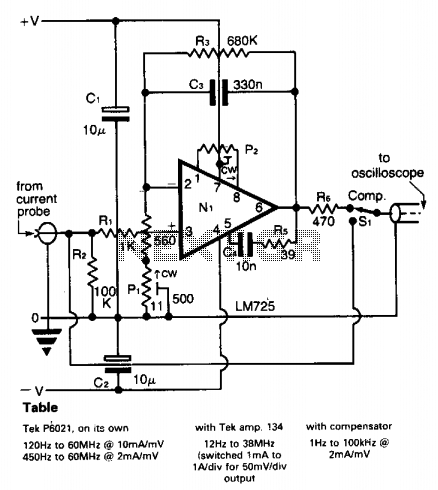
A clamp-on current probe, such as the Tektronix P6021, is an effective tool for displaying current waveforms on an oscilloscope. However, its low-frequency response is somewhat limited, as indicated in the accompanying table. The more sensitive range of the...
This circuit resembles the "Fading Red Eyes" circuit found in the LED section, designed to fade a pair of red LEDs. In this iteration, the lamps are dimmed by adjusting the duty cycle, allowing for the use of higher...
This circuit gradually illuminates a 120VAC lamp over an approximate 20-minute period. A bridge rectifier provides 120V DC to the MOSFET and the 60-watt lamp. A 6.2K, 5-watt resistor along with a Zener diode is utilized to reduce the...
A neon lamp or tube lamp requires high voltage to initiate the ionization of the gas contained within the tube. Once ionization takes place, the voltage decreases to approximately 40 volts. Neon lamps operate on the principle of gas discharge,...

The purpose of this circuit is to power a lamp or other apparatus for a specified duration (30 minutes in this case) and then turn it off. It is particularly useful for reading in bed at night, as it...
The objective of this circuit is to power a lamp or other device for a predetermined duration (30 minutes in this instance) and subsequently turn it off. This functionality is particularly beneficial for reading in bed at night, as...