
Bedside Lamp Timer

This circuit is designed around a simple timer mechanism that utilizes two integrated circuits (IC1 and IC2) to manage the timing and output control. The first integrated circuit (IC1) serves as a light indicator and can be configured to drive a piezo sounder for auditory alerts. The second integrated circuit (IC2) is responsible for generating the timing sequence, utilizing a resistor-capacitor (RC) timing network to control the duration of the lamp’s illumination.
Upon pressing the P1 pushbutton, the circuit initiates the timing sequence, activating the relay to power the lamp. The LED indicator provides a visual cue for the user, illuminating for the initial 25 minutes. The blinking sequence serves as a warning for the user, allowing them to decide whether to extend the reading time or prepare for the lamp to turn off. The circuit's design ensures that during the off state, it draws minimal current, enhancing its energy efficiency.
The use of transistors Q1 and Q2 in an ALL-ON ALL-OFF configuration is crucial for maintaining low power consumption when the circuit is inactive. The reset function on IC2 via pin 12 ensures that the timing sequence can be restarted with each activation of the P1 pushbutton. The oscillation frequency set by R4 and C4 allows for flexibility in timing adjustments, accommodating different user preferences for lamp duration.
Overall, this circuit exemplifies an efficient and user-friendly solution for managing lighting in a bedside environment, providing both functionality and convenience for users who may fall asleep while reading.The purpose of this circuit is that of power a lamp or other apparatus for a given time (30 minutes in this case), and then to turn it off. It`s useful when reading at bed by night, turning off the bedside lamp automatically in case the reader falls asleep.
After turn-on by P1 pushbutton, an LED lights for c25 minutes, but 6 minutes before the tur n-off, start blinking for two minutes, then stop blinking for other two minutes and finally blinks for other two minutes, thus signaling that the on-time is ending. If the user want to prolong the reading, can earn another half-hour of light by pushing on P1. Turning-off the lamp at user`s ease is obtained pushing on P2. Q1 and Q2 forms an ALL-ON ALL-OFF circuit that in the off state draw no significant current. P1 starts the circuit, the relay is turned on and the two ICs are powered. The lamp is powered by the relay switch, and IC2 is reset with a positive voltage at pin 12. IC2 start oscillating at a frequency settled by R4 and C4. With the values shown pin 3 goes high after c30 minutes, turning off the circuit via C3. During the c6 minutes preceding turn-off, the LED does a blinking action by connections of IC1 to pins 1, 2 & 15 of IC2.
Blinking frequency is provided by IC2 oscillator at pin 9. The two gates of IC1 are in parallel to source an higher current. If needed, a piezo sounder can be connected at pins 1 & 14 of IC1. Changing IC2 brand name, varies the oscillation frequency. In particular Motorola`s ICs run faster. Obviously, time can be varied changing C4 and R4 values. 🔗 External reference
Related Circuits
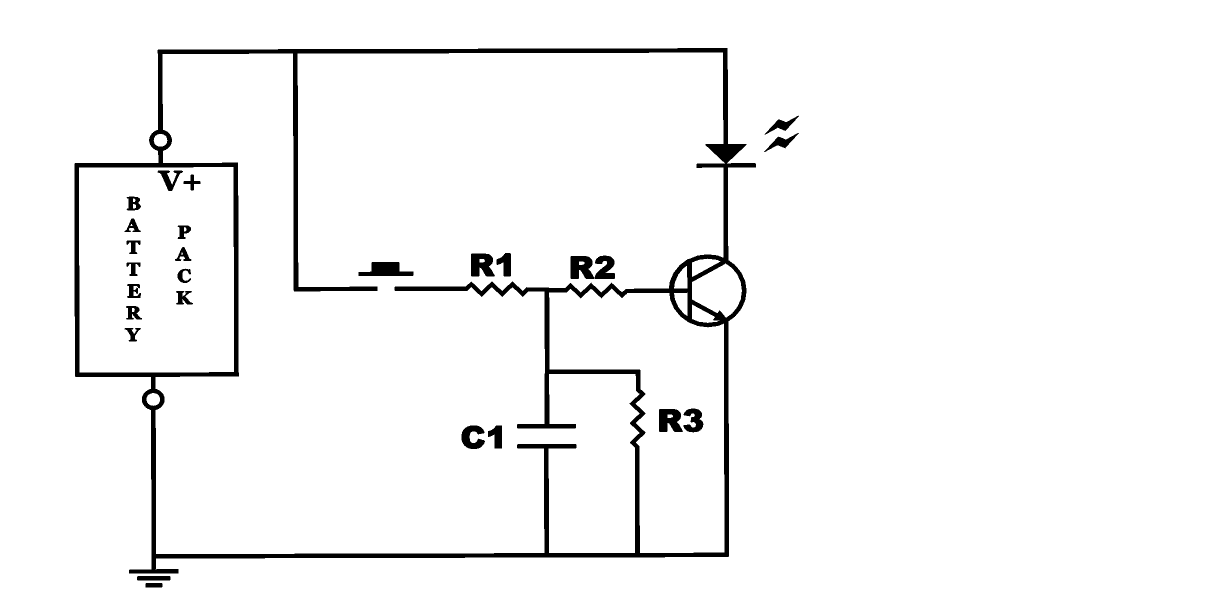
The project involves building an autofade table lamp based on a specific circuit diagram. The actual test circuit is depicted, with a note that resistor R1 from the schematic was omitted, as it was not necessary for the testing...
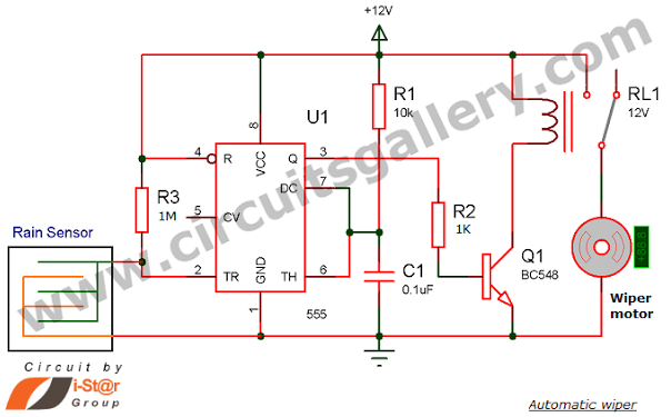
Have you seen Audi, Lexus, or Ford rain-sensing wipers and wondered how they operate in these vehicles? They are controlled by sensors located at the center of the windscreen, which detect raindrops and activate the wiper motor. The functioning...
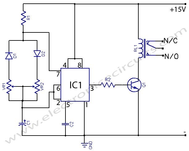
555 Timer with On-Off Delay Circuit. This circuit utilizes the commonly available 555 integrated circuit (IC) to create a timer that allows for time adjustment in both on and off states. The 555 timer is a versatile device widely used...
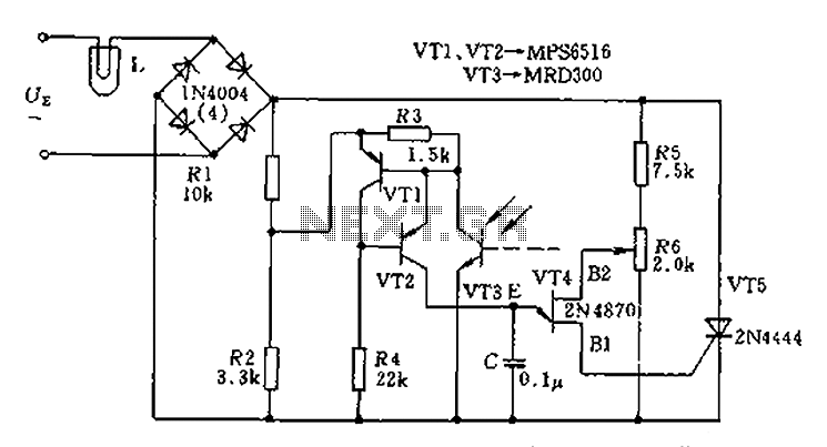
The circuit is designed to stabilize the brightness of lamp L using a thyristor-based AC automatic voltage regulator. The thyristor T5 is connected diagonally across the bridge circuit. The trigger pulses are generated by components VT1, VT2, and VT3,...
This circuit provides a visual 9-second delay using 10 LEDs before closing a 12-volt relay. When the switch is closed, the 4017 decade counter will reset to zero, illuminating the LED connected to pin 3. The output at pin...

The finish line circuit below detects the first of three cars to cross the line and illuminates a 25 watt 120 VAC lamp indicating the winning lane. Three photo transistors are used which can be embedded into the track...