
ve170 monitor repair with led

The described monitor repair process highlights the challenges associated with replacing the power supply for vacuum tube backlighting. The disassembly phase is critical, requiring meticulous handling to prevent damage to the vacuum tubes and their trays. The strategic placement of LEDs is essential for optimal light distribution, with the specified spacing and angling aimed at maximizing illumination efficiency.
The use of a 9-volt battery for testing demonstrates a practical approach to validating the LED configuration before final assembly. The choice of resistors is also pivotal, as they regulate current flow to the LEDs, ensuring they operate within safe limits while providing adequate brightness. The arrangement of LEDs in sets of three, with careful attention to their spacing, is necessary to avoid dark spots on the display.
For improved performance, the suggestion to utilize surface-mount LEDs on a dedicated circuit board represents a significant advancement in design. This approach would facilitate a more compact assembly and potentially enhance the uniformity of the backlighting across the screen. The comparison with laptop displays emphasizes the need for brightness and color accuracy in monitor design, as these factors are critical for user satisfaction.
Future iterations of this project could explore the integration of higher-efficiency LEDs and alternative power supply solutions to further enhance the monitor's performance. Additionally, the implementation of a more sophisticated thermal management system may be beneficial, given the heat generated by high-brightness LEDs. Overall, the project illustrates the complexities of retrofitting older technology with modern lighting solutions, underscoring the balance between cost, labor, and performance.The problem with this monitor is that the power supply for the vacuum tube back lighting dies. The first step is to totally disassemble the monitor into little pieces, then carefully remove the gold colored trays that hold the vacuum tubes. Then carefully remove the tubes themselves without breaking them, like that can be done. The LED`s are spaced at about 1/2 inches apart by using the edge of a cardboard box as can be seen below. This was the test setup using a 9 volt battery, the LED`s are spaced every three holes from each other. The LED`s are wired in sets of 3 with a 12 ohm 1 watt resistor in series with all of the sets of three LED`s.
A 10 ohm to 15 ohm resistor would work just as well. This is what the LED`s look like in the tray. They have to be angled at a 45 degree angle towards the back of the screen in order to fit and it is a very tight fit. I tried to use a flat front LED so it could aim directly up at the screen but did not see any increase in brightness.
This is what it looks like with the bottom tray full of LED`s. There are a total of 27 LED`s in the bottom light tray in this photo. There needs to be about 27 LED`s in each of the trays. The dark areas are where the resistors are located. I no longer put any resistors in the tray for that reason. As you might be able to guess the labor far exceeds the value of the fixed monitor. Also you can see in the photo above that unless you space the LED`s so they are almost touching each other then there will be blank spaces between them. The ideal solution would be surface mount LED`s on a circuit board to provide continuous lighting. The picture below shows what it looks like compared to a laptop. As you can see it is not as bright and the picture has a purple color to it. Even thought the color looks white to the eye it is somewhat blue by comparison. The LED`s used were 3mm 16, 000 MCD bright white LED`s found on EBay. There are brighter LED`s available that might work even better. I tried using the flat top LED`s and they fit better because they are shorter and light the screen more evenly.
Also the resistors can be external, wire all of the LED`s up in parallel sets of 3 each, then use a 10 to 20 ohm resistor externally between it and the 12 volt power supply. 🔗 External reference
Related Circuits
The circuit monitors PC keyboard activity through a five-pin DIN connector J1. When a key is pressed, the keyboard transmits a series of negative-going pulses on pin 2. In conjunction with Q1 and C3, the operational amplifier operates as...
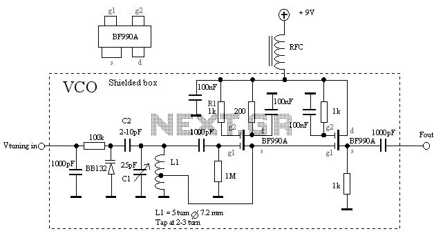
The VCO is based on a Hartley oscillator. The frequency is determined by L1 and capacitor C1. The tuning voltage will change the capacitance in the varactor BB132 which will change the oscillation frequency. The value of capacitor C2...
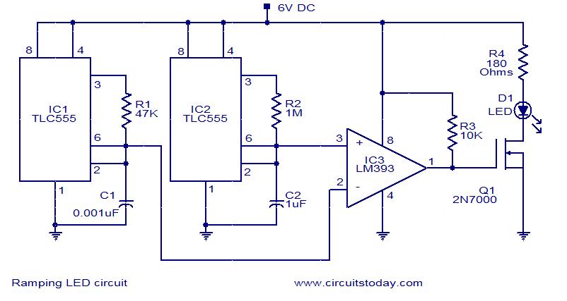
In this circuit, the intensity of the LED varies in a ramping fashion. The circuit comprises three integrated circuits: two 555 timer ICs and one LM393 operational amplifier. IC1 and IC2 are configured as oscillators to generate frequencies of...
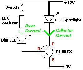
A transistor is an electronic component that allows a small current to control a significantly larger current. This characteristic is valuable in various renewable energy projects and other applications. A basic circuit diagram is provided, featuring a 12V LED...

This is a simple automatic light switch circuit designed for bedrooms. After construction, connect the input terminals of this circuit in parallel to the internal buzzer terminals of a quartz alarm clock. When the clock alarm is activated, the...
Most 24V power systems in trucks, 4WDs, RVs, boats, and similar applications utilize two series-connected 12V lead-acid batteries. The charging system is designed to maintain the total voltage of the two batteries. If one battery begins to fail, the...